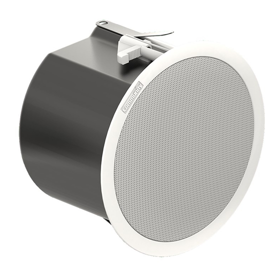
Community C4LP Посібник з монтажу та експлуатації - Сторінка 16
Переглянути онлайн або завантажити pdf Посібник з монтажу та експлуатації для Спікери Community C4LP. Community C4LP 20 сторінок. Commercial design series ceiling loudspeakers

Details for Pre-Installation in a New Drywall
Ceiling
Optional New Construction Brackets are
available for installing loudspeakers in new
construction before drywall or plaster is put
in place. See Figure 17, and refer to the chart
of Figure 2 on page 7 for sizes and model
numbers.
Figure 17. New Construction Bracket for
Drywall or Lath-and-Plaster Installations
The New Construction Brackets support the
loudspeakers in plaster/dry wall ceilings.
Multiple holes in the bracket's two "ears"
permit convenient attachment to nearby
ceiling beams. The drywall typically is
cut with a router-type tool, in which case
the bracket central hole will serve as a cutout
guide for the router bit.
Always attach a safety cable
to one or both seismic safety
tabs in all installations. Failure
to do so could result in injury or even
death in the event of a failure of the
primary mounting support system.
Community Commercial Design Series
Inserting the Loudspeaker Assembly into the
Drywall Ceiling
1. Bring the wiring from the ceiling to the
top of the can and attach it to the terminal
block (see the next Section of this manual for
details). Secure the wiring with the top plate/
strain relief clamp.
2. Before sliding the back can into the ceiling
hole, slightly bend each Drop-Stop installa-
tion assistant tab outward from the back can
1/2 inch (12 mm). Slide the loudspeaker into
the hole. When pressing the unit fully into
place, the two Drop-Stop tabs will spread atop
the tile support bridge rails, and you may
hear them "snap" into position; you can now
continue without having to hold the back can
in place. The illustration in Figure 13 on page
14 shows how the Drop-Stop tabs work, and
is equally applicable with New Construction
Bracket installations in drywall ceiling
3. Locate the two Philips-head can
clamp actuators around the perimeter
of the front lange, and using a #2 Phillips
screwdriver twist each actuator clockwise
until you feel tension as the clamps securely
lock the loudspeaker into the ceiling (refer
to Figures 13 and 14 on page 14). These
clamps open fully to 2.35" (59.6 mm), but
we allow at least 0.60" (15.2 mm) to grab
the Tile Bridge Support Rail atop the ceiling.
Loudspeakers leave the Community factory
with these clamps fully open so that approx-
imately 1.75
be accommodated.
Installation and Operation Manual
(44.4 mm) thick ceilings can
"
Page 16
