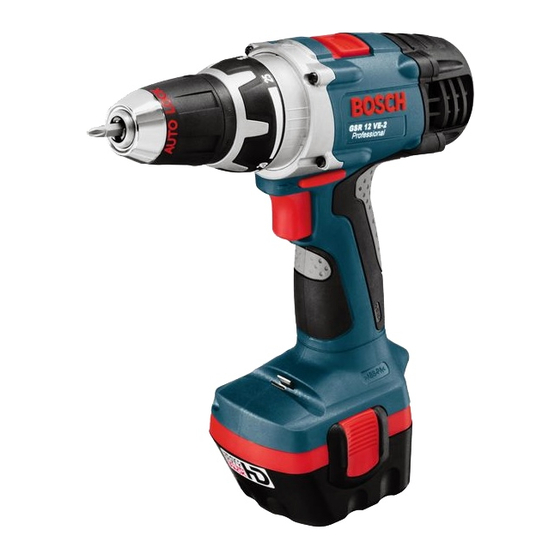
Bosch GSB 12 VE-2 Інструкція з експлуатації Посібник з експлуатації - Сторінка 8
Переглянути онлайн або завантажити pdf Інструкція з експлуатації Посібник з експлуатації для Дриль. Bosch GSB 12 VE-2. Bosch GSB 12 VE-2 10 сторінок. Professional
Також для Bosch GSB 12 VE-2: Інструкція з експлуатації Посібник з експлуатації (10 сторінок), Інструкція з експлуатації Посібник з експлуатації (10 сторінок)
Electric Brake
When releasing the On/Off switch 4 the speed of
the drill chuck is reduced to a stop, thus prevent-
ing the run-on of the tool.
For screwdriving applications, wait until the screw
is flush with the material and then release the On
/Off switch 4. The screw head does not penetrate
into the material then.
Gear Selection, Mechanical
Two speed ranges can be pre-selected with the
gear selector 1:
1st gear:
Low rotational speed, high power.
2nd gear:
High rotational speed, less power.
The gear setting can be changed while the ma-
chine is running, however, not while under load.
It is recommended to carry out the switching
while the machine is at a standstill. If the gear se-
lector 1 cannot be slid into the end position while
the machine is at a standstill, turn the chuck
somewhat or briefly press the On/Off switch 4.
Fully Automatic Spindle Locking
(AutoLock)
The drill spindle is locked when the On/Off
switch 4 is not pressed.
This makes quick and easy changing of the tool
in the drill chuck possible.
The locked drill chuck enables retightening of
projecting screws by using the switched-off ma-
chine as a screwdriver.
Reversing the Rotational Direction
Operate
the
switch 5 only at a standstill.
The rotational direction switch 5 is used to re-
verse the rotational direction of the machine.
However, this is not possible with the On/Off
switch 4 actuated.
a
b
b b b
b b b b
15 • 2 609 932 156 • TMS • 10.09.02
rotational
direction
For drilling and driving in
screws, set the rotational
direction CLOCK-
WISE
.
b
To drive out screws,
switch to the rotational
direction ANTICLOCK-
WISE
.
a
Setting the Torque
Carry out a practical test to determine with which
of the 15 settings of the torque setting ring 2 the
screws are driven flush into the material.
Low setting, e. g., small screws, soft
1
materials.
High setting, e. g., large screws, hard
15
materials.
With the correct setting, the clutch disengages as
soon as the screw is driven flush into the material
or the set torque is reached. Select a higher set-
ting when driving out screws, or set to the "Drill-
ing" symbol.
Drilling and Impact Drilling
Drilling
Set the torque setting ring 2 to the "Drill-
ing" symbol.
Hammer Drilling (GSB 12 – 24 VE-2)
Set the torque setting ring 2 to the
"Hammer Drilling" symbol.
Replacing the Drill Chuck
Before any work on the machine itself, re-
move the battery.
The locking screw 14 secures the drill chuck
against loosening from the drill spindle. Fully
open the chuck and completely unscrew the lock-
ing screw 14 (Note: left-handed thread!) (see
figure
E
).
Loosening the Drill Chuck
(see figure
Place the machine on a stable surface (e. g.
workbench). Hold the machine firmly and loosen
the chuck by turning to the left, as when unscrew-
ing a screw ( ). Loosen a tight chuck by giving
the long end of the Allen key 13 a sharp blow.
Tightening the Drill Chuck
(see figure
The drill chuck is mounted in reverse order ( ).
English - 4
)
C
)
D