Compact Electric CDMR-62 Посібник користувача - Сторінка 4
Переглянути онлайн або завантажити pdf Посібник користувача для Реле Compact Electric CDMR-62. Compact Electric CDMR-62 13 сторінок. Digital line monitoring relay, 3x100v/57v ac

Mains monitoring relay CDMR-62
General information:
The CDMR-62 is a digital line monitoring relay on a micro-controller basis with high measuring accuracy and 13 monitor-
ing functions, which are designated by the following abbreviations:
U< ... Undervoltage stage 1
U<< ... Undervoltage stage 2
U<<<
Undervoltage stage 3
U> ... Overvoltage stage 1
U>> ... Overvoltage stage 2
Relay configuration
See Fig. 3 and Fig. 4 as basic information for configuration through the front control panel, see page 8 for configurations
through serial interface.
Line
/
50.00Hz
57V
57V
57V
Undervoltage U<<
Stage2 K1__4_ <-
Undervoltage
U<
Stage1 K_____ <-
Settings for 3-wire or 4-wire grid
The star voltages are monitored in the 4-wire grid. The triangular voltages are monitored in the 3-wire grid, the star point
will be created internally. The limit values (U<<< ...U>>, Asy) for the star and triangular voltages are stored independently
from each other. Depending on the selected grid type, only the star or the triangular voltage limits are visible and adjust-
able at the CDMR-62 as well as in the PC parameterizing program.
Connection to a 1-phase grid: Connect voltage to the inputs L1, L2 and L3, grid type = "4-wire".
Voltage monitoring U<<<, U<<, U<, U>, U>>
Voltage measurement (root mean square values, digital harmonic filter) includes the star voltages and the phase-to-
phase voltages. The monitoring is sensitive to individual phases (U< excitation if at least one phase is below the limit
value, U> excitation if at least one phase is above the limit value). The undervoltage triggering can be blocked through
input "B" (see section "External blockade input"). When using the measuring voltage as auxiliary voltage, then the mes-
sage relays for U<, U<< or U<<< must be operated inverted, because otherwise undervoltage cannot be reported if the
auxiliary voltage fails.
Important: At least one undervoltage stage >= 70% must be set for standard grid parallel operation applications
because the frequency and vector shift triggering will be blocked below 70%Un and because otherwise there
would be a voltage range for which no triggering can be performed.
Special function:
2-phase sensitivity for the U< switching stage
This special function can be activated using the parameter "U< Trip Logic" in the menu block "General settings".
U< Trip Logic = OFF:
CDMR62e_man_A1.doc
/ Operating instructions
f< ...
f<< ... Under frequency stage 2
f> ...
f>> ...
1.
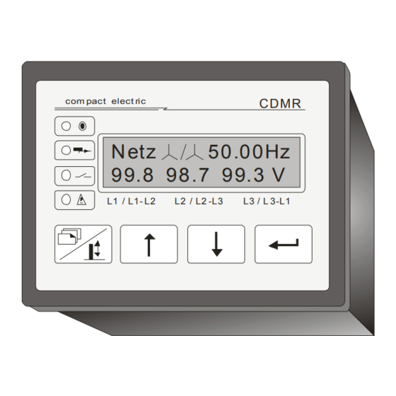
Information: The standard display with the current line values appears when connect-
ing the auxiliary voltage. Starting with this menu, the arrow keys can be used to browse
through all main menus. Using the ENTER button, one gets from the main menus to the
chain of detailed menus
2.
1st Step: Setting the grid type (3/4-wire grid) in the menu block "General settings".
These settings must be established at the start because different data records are allo-
cated to the 3-wire and 4-wire grid voltage monitoring.
3.
2nd Step: Activation and parameterizing of the required monitoring functions:
Selection of the appropriate main menu (example left U<<). The main and detail menus
always include the abbreviation of the respective switching step in the upper right area.
The output relays, which act on the switching stage (e.g. "K1__4_" with effect on K1 and
K4), are always listed on the second line
A switching stage is
4.
Information:
play "K_____" in main menu).
Change of the setup values, see page 5.
Individual phase sensitivity U< Triggering, if at least one phase
undershoot the limit value.
Undervoltage stage 1
Overfrequencies stage 1
Overvoltage stage 2
inactive if no output relay is allocated to it (dis-
Page 4
Vk> ...Vector shift
Asy ... Voltage asymmetry
Wsy ... Angle asymmetry
DRE ...Rotational direction
