Dresser Masoneilan 10000 Series Інструкція з експлуатації - Сторінка 4
Переглянути онлайн або завантажити pdf Інструкція з експлуатації для Блок управління Dresser Masoneilan 10000 Series. Dresser Masoneilan 10000 Series 12 сторінок. Double ported globe valves
1. Introduction
The following instructions are designed to assist maintenance
personnel in performing most of the maintenance required on
the 10000 series valve.
Masoneilan has highly skilled service people around the
world available for startup, maintenance and repair of
our valves and component parts. In addition, a regularly
scheduled training program is conducted to train customer
service and instrumentation personnel in the operation,
maintenance
and
application
and instruments. Arrangements for these services can be
made through your local Masoneilan representative. When
performing maintenance use only Masoneilan replacement
parts. Parts are obtainable through your local Masoneilan
representative. When ordering parts always include Model
and serial number of the unit being repaired. These
installation and maintenance instructions apply to all sizes
and ratings of the Masoneilan 10000 series control valves,
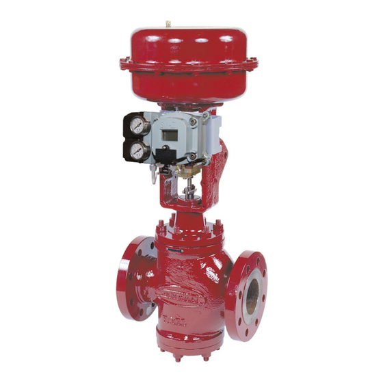
regardless of the type of trim used. The model number,
size and rating of the valve are shown on the identification
tags located on the actuator. refer to figure 1 to identify
valve nomenclature.
2. Unpacking
Care must be exercised when unpacking the valve to prevent
damage to the accessories and component parts. should any
problems arise, contact your Masoneilan representative or
sales office.
3. Installation
The valve must be installed with the flow entering between the
seats. In addition, the upper plug must be installed so that the
larger of the two v-notches in the plug is oriented to face the
inlet of the valve.
3.1 Before installing the valve in the line, clean piping and
Numbering System
1st
2nd
8
Actuator Type*
87 spring Diaphragm:
direct, Air to close
(fail open action)
88 spring Diaphragm:
reverse, Air to open
(fail close action)
note: (*) for valve Travel > 2.5" use Actuator Model 37/38.
Instructions eh10000 - 06/10
10000 series Double Ported globe valves
of
our
control
valves
1st
1
Body Series
Plug Type
10
1. Double seat
Figure 1
valve of all foreign materials, such as welding chips, scale,
oil, grease or dirt. gasket surfaces should be thoroughly
cleaned to ensure leak-proof joints.
3.2 To allow for in-line inspection, maintenance and removal of
the valve without service interruption, provide a manually
operated stop valve on each side of the 10000 series valve
with a manually operated throttling valve mounted in the
bypass line (see figure 2).
3.3 The valve must be installed so that the control substance
will flow through the valve body in the direction indicated by
the flow arrow located on the body or the words in and out
stamped on end connections. In addition, see CAuTIon
above.
3.4 Where insulation of the valve body is required, do not
insulate the valve bonnet.
4. Air Piping
The actuator is designed to accept 1/4" nPT air supply piping.
use 1/4" oD tubing or equivalent for all air lines. If the air line
exceeds 25 feet in length or if the valve is equipped with volume
boosters, 3/8" tubing is preferred. All connections must be free
of leaks.
Do not exceed loading pressure indicated on the warning tag
located on the diaphragm cover. If no tag is present please
consult the actuator instruction manual or consult the factory.
3rd
2nd
0
Control Characteristics
3. equal Percentage
6. Quick opening
7. linear
2
Figure 2
4th
5th
Seat Type
2. Down
seating