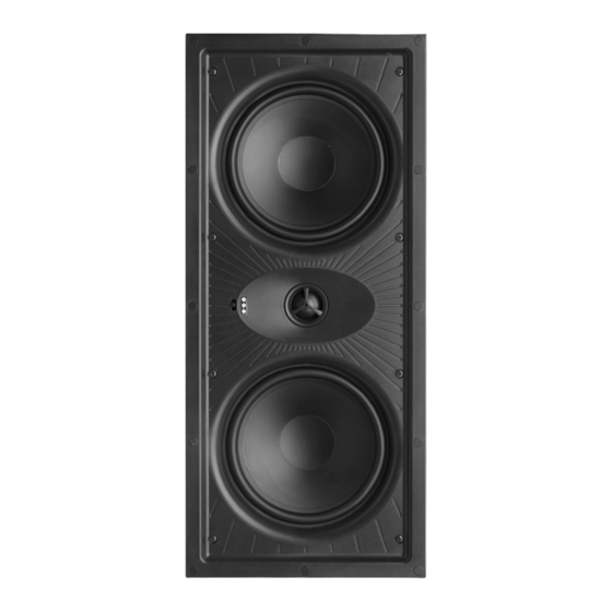
Atlantic Technology IW Series Інструкція з експлуатації - Сторінка 3
Переглянути онлайн або завантажити pdf Інструкція з експлуатації для Спікери Atlantic Technology IW Series. Atlantic Technology IW Series 4 сторінки. Trim bezel in-wall loudspeakers

e spacing of the le-right
speakers can be a little wider
than with 2-channel stereo
speakers, since in a theater
system, the center channel
speaker reproduces the on-
screen effects and anchors
the center image. Le-right
spacing of about 8 to10 feet usually works well.
Surround Speakers: In order to achieve optimum performance we
strongly recommend Atlantic Technology Dipole or TriVector™ surround
speakers. If you are using our dedicated surround speakers please follow
the placement recommendations included in their installation instructions.
Non-Dipole Surrounds: e most realistic surround effects occur when
the listener can't localize the actual location of the surround speaker. If
you decide to use the In-Wall eater System speakers as surround
speakers, mount them above the listeners' ears, slightly behind the lis-
tening area either on the side or rear walls.
Installation of IW-105LCR/110LCR in New Construction
Atlantic Technology offers optional new construction brackets (IN-NC-
105LCR/110LCR) to ease installation in new construction. Instructions
for its use are included with that kit.
Installation of IW-105LCR/110LCR in Existing Construction
Removing and Installing the Grille
Remove the grille from the speaker using the supplied tool, an awl, at the
point of a drywall screw in a grille opening near one of the grille corners.
Slowly pry the grille out, being careful not to damage the speaker's frame
or its finish.
To re-install the grille later, fit it carefully over the baffle. e trim-bezel
grille is designed to be held in place with magnets and fit snugly over the
speaker. Please take your time and use care when installing the grille.
Cutting the Opening
Aer determining the best location for the speaker as outlined above,
WARNING Exercise extreme care before making any wall cuts to ensure that you
will not cut through any wires, pipes, or other items that may be in the wall. You may
sometimes, but not always, be able to determine the approximate location of wires
and pipes by looking at the locations of nearby outlets and plumbing. But their location
or absence is never an assurance that there is not something within the wall cavity.
Installing the Speaker
e clamping mechanism allows the wall material to range from
1
1
/
˝ (13 to 38 mm) in thickness. ere must be a minimum depth be-
4
hind the wall face of 3
5
/
˝ (92 mm). As noted above, be sure to keep the
8
edges of the cutout at least
tion, as the rotating clamps will not operate properly if you don't. Insert
use the enclosed
template to cut the
proper size hole.
(185mm x 285mm)
(185mm x 455mm)
1
/
˝ (13 mm) away from any stud or obstruc-
2
the frame into the cutout and using a level or square care-
fully align it so it is level. Tighten the mounting screws,
which will cause the attached clamps to rotate and position
themselves properly behind the wall.
Continue to tighten until the frame is snug in the wall. You
want the bezel to conform to the wallboard, and the frame
not to rattle from the speaker's vibration, but be very careful
not to overtighten the screws.
Painting the Grille and Frame
fully pulling diagonally across the length of the grille. Lay
the scrim on the cutout template and store it in the provided
plastic bag to protect the scrim from indirect paint spray and
damage while the grille is being painted.
You can now paint the grille and trim bezel. Be sure to keep
the holes in the grille free of paint. An airless sprayer or
spray paint will work best. Aer the paint is dry you can
reattach the scrim and reinstall the grille.
Speaker Connection and Assembly
IW-105LCR
1
1
7
/
˝ x 11
/
˝
4
4
Front Panel Controls
HF (High Frequency) Level Control
IW-110LCR
is control adjusts the relative level of high frequency out-
7
1
/
˝ x 17
7
/
˝
4
8
put to compensate for varying room acoustics or placement
behind a screen.
"0" is for rooms of average absorptive characteristics.
"–" should be used in rooms that are highly reflective, with
1
/
˝ to
2
hard floors and exposed windows.
e setting of the HF control is mostly a matter of personal
taste, so try it in all three positions and see which one is pre-
ferred.
e grille can be painted to
blend into virtually any décor.
e grille has a removable scrim
behind the metal to conceal the
drivers. Before painting remove
the grille, carefully remove the
fabric scrim from the inside of
the metal grille using a tweezers
or needle-nosed pliers, starting at
a corner of the grille and care-
Strip about
mm) of insulation
from the connecting
wires. Connect them
to the appropriate
push terminal, being
careful to observe
polarity (positive to
the red terminal,
negative to the black
terminal).
"+" is for absorptive, acoustically "dead"
rooms (or when the speaker is behind a
movie screen). Use this position to in-
crease the HF level and restore the proper
sparkle and liveliness to the sound.
1
/
˝ (13
2
