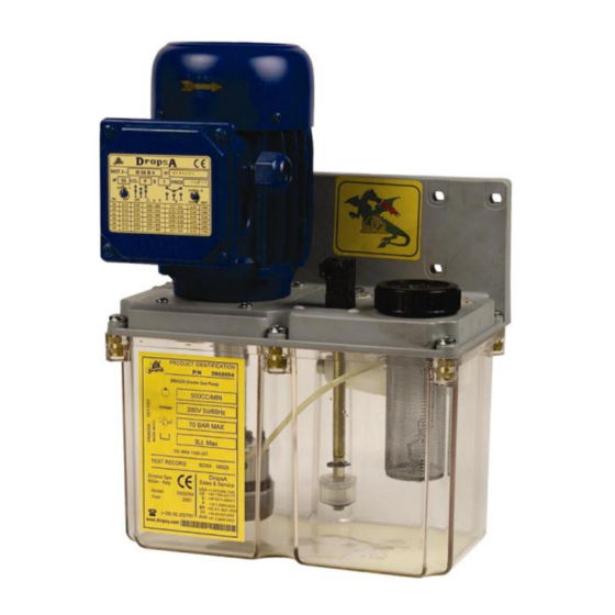
DROPSA Dragon Series Посібник з експлуатації та обслуговування - Сторінка 7
Переглянути онлайн або завантажити pdf Посібник з експлуатації та обслуговування для Водяний насос DROPSA Dragon Series. DROPSA Dragon Series 12 сторінок.
Також для DROPSA Dragon Series: Посібник з експлуатації та технічного обслуговування (13 сторінок)

9. MAINTENANCE PROCEDURE
The pump was designed and built in order to minimize maintenance requirements.
To simplify maintenance, it is recommended to install it in an easy to reach position.
Periodically check the pipe joints to detect any leaks. Furthermore, always keep the pump clean to be able to quickly
detect any leaks or defects.
If necessary, replace the refilling filter code 3130180
It is necessary to periodically check as follows:
INSPECTION / MAINTENANCE OPERATION
Condition of lubrication
Cleansing of the loading filter and of the suction filter
Cleansing of the tank bottom if there are deposits
The machine does not require special equipment for any inspection and/or maintenance activity. It is however
recommended that the equipment used be suitable and in good condition (DPR 547/55) so as to avoid damage to
people or parts of the machine.
WARNING: Prior to any maintenance, be sure that the power and the hydraulic supplies are off and
there is no residual pressure in the main/branch pipe.
In the case of persistent problems and/or doubts, do not disassemble parts of the machine to trace the origin, instead
contact the technical office of DROPSA S.p.A.
10. DISPOSAL
During maintenance or disposal of the machine care should be taken to properly dispose of environmentally sensitive items
such as oils or other lubricants. Refer to local regulations in force in your area.
When disposing of this unit, it is important to ensure that the identification label and all the other relative documents are
also destroyed.
11. ORDERING INFORMATION
11.1 Standard Versions:
MOTOR
THREE-PHASE MULTI-
VOLTAGE
MOTOR
MONOFASE
11.2 Accessories
PART NO.
20566
20564
3291028
3291022
1639077
1639087
3085230
FLOW RATE
TANK
350
500
FLOW RATE
TANK
350
500
Pressure gauge
(0
25 bar)
Pressure gauge (0
100 bar)
Pressure switch (low pressure)
Pressure switch (high pressure)
Control panel
Control panel
Revolving terminal
WORK CYCLES
1000
2000
4000
SYSTEM 01
3
3901050
6
3901052
3
3901054
6
3901056
SYSTEM 01
3
3901070
6
3901072
3
3901074
6
3901076
DESCRIPTION
Depending on the lubrication system, two versions may be
assembled: 0
bar for higher pressures.
Depending on the lubrication system, two versions may be
assembled: 10
bar for higher pressures.
It is also possible, as an accessory to the pump, to have a
control panel entitled "VIP", which allows the various
operating parameters to be controlled: manostat and level
alarms, as well as the operating and pause cycle.
Provisions must be taken for this when the pressure gauge
and manostat are installed.
SYSTEM 33V
SYSTEM 26
3902050
3903050
3902052
3903052
3902054
3903054
3902056
3903056
SYSTEM 33V
SYSTEM 26
3902070
3903070
3902072
3903072
3902074
3903074
3902076
3903076
25 bar for uses with low pressures, 0
20 bar for uses with low pressures, 20
100
50
7
