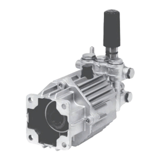
Annovi Reverberi XJV3G20E-F8 Інструкція з експлуатації та посібник із запчастин - Сторінка 6
Переглянути онлайн або завантажити pdf Інструкція з експлуатації та посібник із запчастин для Водяний насос Annovi Reverberi XJV3G20E-F8. Annovi Reverberi XJV3G20E-F8 18 сторінок. Plunger pumps

Operating Instructions and Parts Manual
Plunger Pumps
Special Features (continued)
Oil Seals and O-rings: All are
constructed of Buna-N rubber. The oil
seals have stainless steel garder springs
to assure constant tension on the
sealing surface.
Oil Capacity: 4.5 oz.
Extra Features
Dyno Proven: All pumps are dyno
tested to assure the theoretical design
meets the actual design.
Valve Design: Each pump series has a
valve design that optimizes its highest
efficiency.
Wet End Repair: Very simple no
special tools required.
Mounting Flanges: Gasoline SAE
J609a flange. Refer to breakdown.
Design: Using advanced fluid handling
design programs. Overall pump
efficiency is increased.
Installation
1.
Install the shaft key into the keyway
and apply a light coating of anti-
seize on the engine shaft and key.
2.
Align the two key ways and push
the pump completely onto the
engine.
3.
Install all
four (4) bolts
and tighten
evenly. (See
figure 4)
4.
Remove the
red shipping
Available from Allparts Equipment and Accessories - 1-877-475-5660 - www.allpartsinc.com
oil cap and
install the black
crankcase vent
cap. (See figure 5)
5.
Install the
appropriate water inlet and
discharge fittings.
6.
Connect the water supply hose and
high-pressure discharge hose/spray
gun.
7.
Turn on the water supply.
8.
Open the spray gun to purge the
system of any air.
9.
Start the engine.
10. If necessary adjust the engine speed
and unloader valve.
Unloader Adjustment Steps
Please follow these easy steps to adjust
the pressure:
Step 1: Remove black cap
Step 2: Loosen nut (See
Step 3: Turn brass (See
Step 4: Install a liquid filled
Figure 4
SJ & XJ Series Pumps
(See figure 6 ref. no.
46)
figure 6 ref. no. 3)
with 10mm wrench.
figure 6 ref. no. 4)
clockwise until it
stops.
pressure gauge in the
discharge line. The gauge
should be placed between the
unloader discharge fitting and
high-pressure hose.
Figure 5
Figure 6
NORTH
AMERICA
First Choice When Quality Matters
