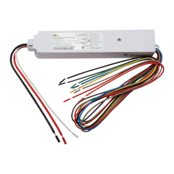
Daintree GE Current WA100-PM Посібник з монтажу
Переглянути онлайн або завантажити pdf Посібник з монтажу для Адаптер Daintree GE Current WA100-PM. Daintree GE Current WA100-PM 19 сторінок. Wireless adapter

Daintree
®
Wireless Adapter
(WA100-PM)
BEFORE YOU BEGIN
Read these instructions completely and carefully.
Save these instructions for future use.
WARNING
Risk of electrical shock. Disconnect power before servicing or
installing product.
Install in accordance with National Electric Code and local codes.
The Daintree WA100-PM Wireless Adapter forms part of the
Daintree Networked wireless controls solution for smart
commercial and industrial buildings. It transmits and receives
messages over the wireless ZigBee
The WA100-PM is an AC powered device that provides On/Off
switching as well as 0-10V analog dimming control for
LED drivers and ballasts.* It also provides power for low voltage
occupancy sensors, photosensors (daylight harvesters),
wall switches, and control signals while it provides the wireless
adaptation that enables them to communicate with the
rest of the wireless control solution. The control signals to and
from these connected devices pass between the WA100-PM
and the Wireless Area Controller in Daintree Controls Software
(DCS) web application.
1
Installation Process
1. Disconnect power before installation. Turn off all power
to affected light fixtures by turning off circuit breakers.
Confirm that power is off at all light fixtures before
continuing installation.
2. Set the WA100-PM DIP switches to support the device(s)
being connected to it. See DIP Switch Settings (page 2).
3. IMPORTANT: Affix the small label with 4-5 digits of the
WA100-PM's IEEE address on the floor Plan to indicate
its location.
4. Mount the WA100-PM in the driver cavity of the light
fixture, or external to the light fixture, or to a junction box
approved for the application. See Mounting (page 12).
5. Connect low voltage wiring from the WA100-PM to the
driver, switch(es) and/or sensors as appropriate for your
application. See Wiring (pages 3-11). Cap any unused wires.
network and controls lights.
®
Risk of injury. Wear safety glasses and gloves during installation and
servicing.
6. Connect line voltage wires from the supply circuit to the
WA100-PM and to the driver as shown in Wiring. Cap any
unused wire.
7. Check load circuits then turn on the circuit breakers to power
up the WA100-PM. The light connected to the WA100-PM turns
On when power is initially applied (and when power is restored
after a power failure).
8. Ensure the WA100-PM green Power
9. Press and hold the blue RESET button on the WA100-PM for
3 seconds to reset the unit. Release the button when the green
Joined LED and the red Error LEDs begin flashing.
10. Perform the installation test appropriate for your application.
See Installation Tests (pages 13-14)
Error/Test — On when the Wireless Adapter is in an error state.
Flashes to indicate unit Reset and during Installation Test Mode (red).
Joined — On when the Wireless Adapter has joined a ZigBee
Flashes to indicate Reset and during sensor Installation Test Mode (green).
Power — On when power is applied to the Wireless Adapter (green).
Installation Guide
WA100-PM | DT113
CAUTION
LED is On.
LED Indicators
Error
Joined
Power
Reset
LED
LED
LED
Button
network.
®
