Anritsu Company VectorStar ME7848A-0240 Посібник із швидкого старту - Сторінка 7
Переглянути онлайн або завантажити pdf Посібник із швидкого старту для Вимірювальні прилади Anritsu Company VectorStar ME7848A-0240. Anritsu Company VectorStar ME7848A-0240 17 сторінок. Opto-electronic network analyzer systems
Також для Anritsu Company VectorStar ME7848A-0240: Посібник із швидкого старту (15 сторінок)

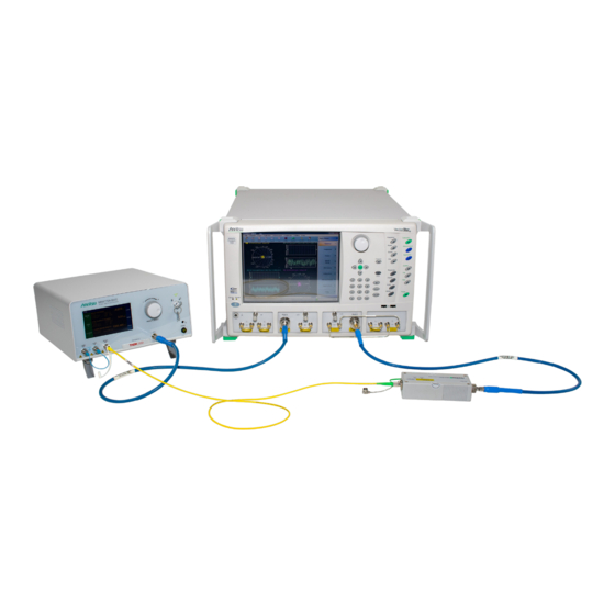
The user's DUT (an E/O, O/E or O/O device) would substitute into one of the positions shown in the figure and
the remaining system components calibrated or de-embedded out to reveal the DUT response. The MN4765B
can also be connected to VNA Port 1 (and E/O converter to VNA Port 2) if desired.
Figure 2.
Common Color-coding of Patch Cord Ends (green often for FC/APC (angled) and yellow or white often
for FC/PC (non-angled))
The cable on the left (green boot) of
MN4765B O/E module. The two other cables (yellow and white boots) are typical of FC/PC connectors; these
ends should be used with the MN4775A E/O converter. Other lasers and modulators/converters may be
connectorized differently.
The MN4775A (and equivalent units) contain a laser and are accompanied by a warning label like that shown
in
Figure
3. The MN4775A-007x/011x are class 1M and the MN4775A-0040 is class 3B (due to the shorter
wavelength).
Figure 3.
Laser Warning Labels Examples
In addition to the above basic setup, it is possible to improve dynamic range of the measurement in certain
frequency ranges but altering some basic connections to effectively 'reverse' the port 2 test couplers in the VNA
(connections shown in
panel, existing loops are simply rotated 90 degrees and reconnected. For the front panel, semi-rigid cables are
included in the accessory kit to help accomplish this task that make use of the loop access points provided by
options 51/61/62 in the VNA. In the common configuration, we are much more interested in S21 than S12, so by
reversing the port 2 coupler we improve the noise floor for S21 at the expense of drive power for S12.
ME7848A/E QSG
Figure 2
is typically of an FC/APC connector which should be used with the
Figure 4
and
Figure
5). This does not apply to the 110 GHz -0x1x systems. On the rear
PN: 10410-00777 Rev. C
2. System Connections
QSG-7
