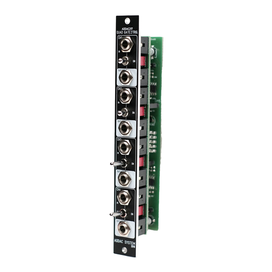
ADDAC System ADDAC217 Посібник з монтажу - Сторінка 3
Переглянути онлайн або завантажити pdf Посібник з монтажу для Синтезатор ADDAC System ADDAC217. ADDAC System ADDAC217 8 сторінок. Quad gate 2 trigger

ADDAC217 Assembly Guide
STEP 1:
Start by locating the 2 capacitors, notice the orientation printed on the pcb.
Tip: soldering these caps is easy, just place a dab of solder on the pad on your right (left pad if you're
left handed) and then, with the help of a tweezer, put the capacitor in place and reflow the previously
tinned pad to melt the solder while pushing the capacitor down. Then solder the other pad.
Follow up by locating and soldering the 78L05 Voltage Regulator, notice the orientation printed on the
pcb. After soldering trim the excess legs.
ADDAC SYSTEM
page 3
