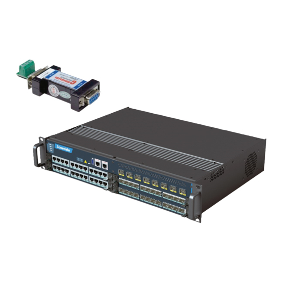
3onedata ICS5556 Series Посібник зі швидкого встановлення - Сторінка 2
Переглянути онлайн або завантажити pdf Посібник зі швидкого встановлення для Перемикач 3onedata ICS5556 Series. 3onedata ICS5556 Series 3 сторінки. Modular layer 3 ethernet switch

Notice Before Mounting:
Don't place or install the device in area near water or
moist, keep the relative humidity of the device
surrounding between 5%~95% without condensation.
Before power on, first confirm the supported power
supply specification to avoid over-voltage damaging
the device.
The device surface temperature is high after running;
please don't directly contact to avoid scalding.
【Rack-mounting】
Step 1
Select the device mounting position and ensure
enough mounting size is reserved.
Step 2
Put the device on the plane plate of the rack, and
install the left and right lugs on the rack with 4
screws.
Step 3
Check and confirm the product is mounted firmly
on the rack, mounting ends.
【Disassembling Device】
Step 1
Power off the device.
Step 2
Unscrew the fixed mounting lug screw on the
rack.
Step 3
Shift out the device from rack, disassembling
ends.
Notice before power on:
Power ON operation: First insert the power supply
terminal block into the device power supply interface,
then plug the power supply plug contact and power on.
Power switch "—" means power ON, "O" means
power OFF.
Power OFF operation: First, put the powers switch to
the "O" side and then disconnect the power supply.
Finally disconnect the connector between the device
and the power cord. Please notice the operation order
above.
【Power Supply Connection】
The device frame provides two power modules,
adopts AC power socket with switch, and
supports Power 1 and Power 2 inputs. The
series of device supports redundant power
supply, two power supply can work at the same time. The
device will still run non-stop when one power supply fails.
AC power supply range: 100~240VAC.
【RESET Button】
RESET button can be used to reboot the device
and restore factory defaults. The operation is as
follows: press the button for 1~2s and release it, and the
device will restart automatically; Press and hold the RESET
button for 3~4s and release it, and the device will
automatically restore the factory defaults.
【USB Port Connection】
The device frame provides one Type-A USB2.0
interface, which can be connected to an
external USB flash disk to import or back up the switch
configuration file.
【Console Port Connection】
The device frames provides 1 program debugging
port based on RS-232 serial port which can
conduct device CLI command management after
connecting to PC. The interface adopts RJ45 port, the RJ45
pin definition as follows:
Pin No.
2
3
Definition
TXD
RXD
【MANAGER Connection】
The device frame provides one MANAGER port,
that is Gigabit Ethernet interface, for device
network management.
【Checking LED Indicator】
The device frame provides LED indicators to monitor the
device working status with a comprehensive simplified
troubleshooting; the function of each LED is described in
the table as below:
LED
Indicate
Description
Power supply is running
ON
normally
PWR1-
PWR2
Power supply is disconnected
OFF
or running abnormally
Power supply or port link has
ON
alarm
ALM
Power supply and port link
OFF
have no alarm
ON
Device is not started or
abnormal
Blinking
The device is running
RUN
normally
OFF
The device is powered off or
the device is abnormal.
Port has established a valid
ON
network connection
G1-G12,
Port is in a network
X1-X8,
Blinking
communication status
MANAGER
Port hasn't established valid
OFF
network connection.
【Logging in to WEB Interface】
5
GND
