ATX Q series Посібник з монтажу та експлуатації - Сторінка 7
Переглянути онлайн або завантажити pdf Посібник з монтажу та експлуатації для Підсилювач ATX Q series. ATX Q series 18 сторінок. Qpair redundancy switch amplifier system

Alarms:
a)
Rear of Chassis:
Form C contacts: C for common, NO for normally open, NC for normally closed.
Description: A contact closure from the NO connection to the C connection is present when the unit is in operation
and under power. When any failure occurs the contacts will switch to a closure between the NC connection and the
C connection. A failure is defined as an RF change that causes a switch to be made, or any device failure, including
either power supply or either RF amplifier.
b)
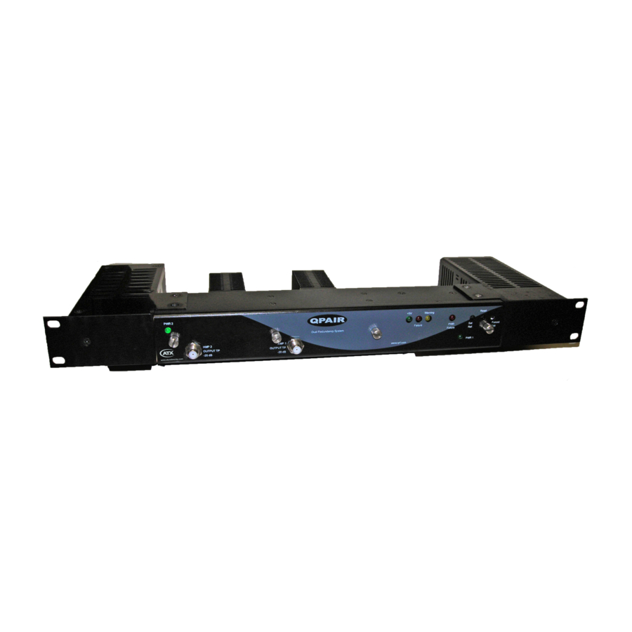
Front of Chassis: (refer to Figure 1 for this section)
Green LED: 5V power on
Yellow LED (warning):
• On continuous: using reference levels stored in EEPROM
• Flashing (1/sec) slow: needs to set reference levels. Normal on power-up or reset.
• Flashing (3/sec) fast: switched to the secondary amplifier when pushing and holding the FORCED SW button.
Red LED (Failure):
• On continuous: primary amp failure. Signal has been switched to the secondary amplifier by the system.
• Flashing (1/sec) slow: secondary amp failure
• Flashing (3/sec) fast: input signal low or primary amp and secondary amp failure.
Red LED (PWR Failure)
• On continuous: power supply 1 failure
• Flashing (1/sec) slow: power supply 2 failure
RF Detector Test Point: (hidden behind the front cover between the PWR failure LED and the Set Ref. button)
• AMP1 RF Level Detector: DC level proportional to the primary amp RF output level.
• AMP2 RF Level Detector: DC level proportional to the secondary amp RF output level.
Recessed Push-Button Switches:
• Reset: restarts the microcontroller program
• Set Ref: stores the levels as references and start monitoring amplifiers and power supplies.
• Forced SW: forces a switch to the secondary amplifier. Facilitates set-up of RF levels.
Q-Series
Amplifiers – QPAIR Redundant Amplifier System – Installation & Operation Manual
®
CHAPTER 1: DESCRIPTION OF INTERFACES
1-3
