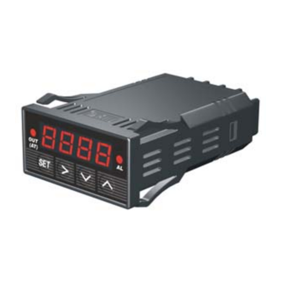
Auber Instruments SYL-1512A Інструкція з експлуатації - Сторінка 6
Переглянути онлайн або завантажити pdf Інструкція з експлуатації для Регулятор температури Auber Instruments SYL-1512A. Auber Instruments SYL-1512A 7 сторінок.

B) To stop the auto-tuning, press and hold
PID parameters value are resumed,
6. Terminal Wiring (back view)
The polarity of power at terminal 1 and 2 do not matter.
Figure 7. Wiring diagram with thermocouple (TC) input on the left and RTD input on the right. Please
note that if the RTD is connected by two wires instead of three wires (for short distance application), the
terminal 6 and 7 need to be shorted.
7. Application Example
A furnace that can operate in the 0℃~1000℃ range needs to be controlled at 800℃. Alarm will go
off if T > 850℃, Power source is 220VAC, Heating element is switched by a SSR。 K type thermocouple
is used as the temperature sensor.
a) Wiring diagram
b) Parameter setting,
(Inty)=K, (outy)=2, (Caty)=0, (PSb)=0, (rd)=0, (CorF)=0, (FILt)=0
Auto-tunig is used to set the PID parameters.
(SV)=800℃, (AH1)=850℃, (AL1)=848℃
Power up the controller. Press and hold the
the Auto-tuning. When the "AT" stops blinking, the new PID parameters are generated for the
system. The controller is in normal operation mode. The furnace will be maintained at 800℃。
For accessories, please check our web site at
key until "AT" indicator stops blinking. Then, the previous
Figure 8
key until "AT" starts to blink. The controller starts
www.auberins.com
6
