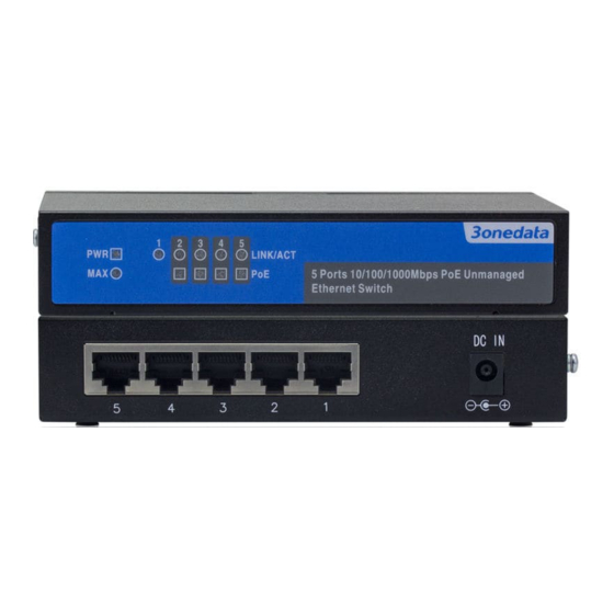
3onedata PS1005G-1GT-4POE Посібник зі швидкого встановлення
Переглянути онлайн або завантажити pdf Посібник зі швидкого встановлення для Перемикач 3onedata PS1005G-1GT-4POE. 3onedata PS1005G-1GT-4POE 2 сторінки. Poe ethernet switch

PS1005G-1GT-4POE
PoE Ethernet Switch
Quick Installation Manual
3onedata Co., Ltd.
Address:
3/B, Zone 1, Baiwangxin High Technology
Industrial Park, Song Bai Road, Nanshan
District, Shenzhen, 518108, China
Website:
www.3onedata.com
Tel:
+86 0755-26702688
Fax:
+86 0755-26703485
【Package Checklist】
Please check whether the package and accessories are intact
while using the switch for the first time.
1.
Switch x 1
2.
Quick installation manual
3.
Power adapter
4.
Warranty card
5.
Certification
If any of these components are damaged or lost, please
contact our company or franchisers, we will solve it ASAP.
【Product Overview】
The product is an unmanaged desktop PoE Ethernet switch.
Model is PS1005G-1GT-4POE (1 Gigabit copper port + 4
Gigabit PoE copper ports).
【Panel Design】
Main view
Rear view
1.
Device power supply connection status indicator
2.
PoE total power status indicator
3.
Ethernet port connection status indicator
4.
PoE power supply output status indicator
5.
10/100/1000Base-T(X) PoE copper port
6.
10/100/1000Base-T(X) copper port
7.
DC power supply input socket
【Mounting Dimension】
Unit: mm
Notes before mounting:
Don't place or install the device in moist area or near
water, keep the relative humidity of the device
surroundings between 10%~90% without condensation.
Before power on, first confirm the supported power
supply specification to avoid over-voltage damaging the
device.
The device surface temperature is high after operating;
please don't directly contact to avoid scalding.
【Wall Mounting】
Mounting the device
Step 1
Place the device on the device mounting wall for
reference or refer to the mounting dimension, and
then mark the position of 2 screws.
Step 2
Fix 2 screws on the wall and reserve 2mm gap.
Step 3
Hang the device on 2 screws and slide down,
mounting ends.
Disassemble the device
Step 1
Power off the device.
Step 2
Lift the device upward slightly, and then take out
the device, disassembling ends.
【Power Supply Connection】
DC power supply input
The device provides 1 channel DC power supply input
and adopts DC round head (inner circle is positive
pole and external circle is negative pole).
Power supply: 51VDC.
Notes:
Power ON operation: first connect the power terminal
block of power line to the device power interface, and
then power on.
Power OFF operation: first unpin the power plug, and
then remove the wiring part of terminal block. Please
note the operation order above.
【Checking LED Indicator】
The device provides LED indicators to monitor the device
working
status
with
a
comprehensive
troubleshooting; the detailed status of each indicator as the
table below:
LED
Status
Description
Power supply is connected and
ON
running normally
PWR
Power supply is disconnected and
OFF
running abnormally
simplified
