ADDER AdderLink LPV Посібник користувача - Сторінка 2
Переглянути онлайн або завантажити pdf Посібник користувача для Подовжувач ADDER AdderLink LPV. ADDER AdderLink LPV 2 сторінки.

Connecting your AdderLink LPV
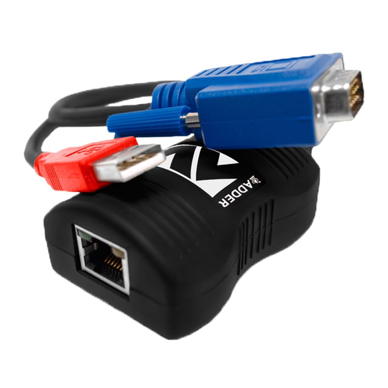
Local unit
1 Connect the plugs to the video output
and a vacant USB port on the computer.
Note: The USB connection provides only
power for the units.
2 Attach one end of the link cable to the
socket at the end of the unit.
IMPORTANT:
• Use only screened (FTP) cable to connect the two units. For cable runs greater
than 50m, low skew cable may also be required to avoid colour fringing ef-
fects within the video image.
• Do not connect the local unit, via CATx cable, to anything other than the remote
unit.
Note: The default DDC data held within the unit supports a range
of common video resolutions. However, some graphics adapters
will choose the highest declared resolution and then scale their
video output to suit, which can result in poor image qual-
ity. If you experience poor quality video, follow the
instructions in the 'DDC information' section to
harvest DDC data from your display screen.
Video and USB
connections to the
host computer
Video connection
to the display
screen
Remote unit
1 Connect the video plug to the socket
on the display screen.
2 Attach the other end of the link cable
to the socket at the end of the unit.
Video sharpness adjustment
The remote module has a video adjustment to
control picture sharpness on the display screen.
To adjust video sharpness
1 On the computer, display a suitable high
contrast image (ideally with one or more black
vertical lines on a white background (e.g. a
capital 'H' at 72 points in a word processor).
2 Insert a small screwdriver into the adjustment
screw on the side of the remote module.
3 Turn the screw fully clockwise - you should see
a bright white shadow to the right of your high
contrast image
4 Turn the screw anti-clockwise until the white
shadow disappears and the edges of your im-
age become sharp.
DDC information
DDC information is not sent from the remote unit. Instead, the local unit holds a standard set
of DDC details which are suitable for most display screens. If the standard details are not suit-
able, temporarily connect the local unit directly to the display screen that is to be emulated and
power on the screen. Note: The local unit must be powered via its USB connection.
If the DDC information is different to that already held, the yellow indicator will flicker rapidly
for 2 to 3 seconds while the new information is stored.
If a problem occurs while attempting to harvest DDC information, the yellow indicator on the
local unit will show a number of distinct flashes. Note the number of flashes in case you need
to contact technical support, but otherwise retry the procedure.
Power control
IMPORTANT: Do not connect the local unit, via the CATx cable, to anything other than the
remote unit.
Low voltage power for the remote unit is fed via one of the pairs within the cable. The local
unit always performs a check before applying power, which is shown by flashing the yellow
indicator. When power is applied, the yellow indicator will remain on.
The local unit will disable the power and begin flashing its yellow indicator if:
• The cable is disconnected
• Line power is overloaded
If the host computer goes into standby (turns off the display screen by disabling sync pulses, as
is usually the case) the local unit will disable line power and go into a low power mode after a
period of approximately 16 seconds. It will not attempt to check the line or turn power back
on. The yellow indicator will remain off until video input is restored.
High contrast
Black or bright white
black character on
shadow on the right
white background
indicates the need for
sharpness adjustment
