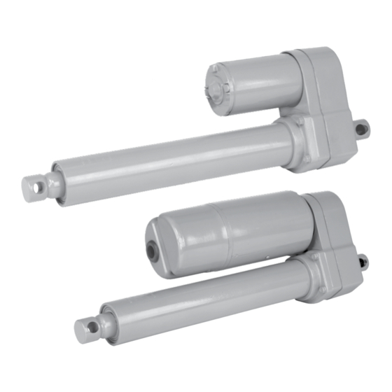
Duff-Norton TAC05-1D20-18 Інструкції з монтажу, експлуатації та обслуговування - Сторінка 4
Переглянути онлайн або завантажити pdf Інструкції з монтажу, експлуатації та обслуговування для Контролер Duff-Norton TAC05-1D20-18. Duff-Norton TAC05-1D20-18 12 сторінок.

Available Models
Clutch
TAL05-1A10-#
TAP05-1A10-#
TAL05-2A10-#
TAP05-2A10-#
TAC05-1D20-#
TAC05-2D20-#
Limit
Available Models
Switch
TAL10-1A20-#
TAP10-1A20-#
TAL10-2A20-#
TAP10-2A20-#
# = Actuator stroke. Standard strokes are 4, 8 and 12 inches (101, 203 and 305 mm)
Custom stroke lengths are available.
Performance figures at rated load. Data is approximate.
2-1. Clevis Connections
Refer to Fig. 1-1 for appropriate mounting dimensions.
The actuator should be connected with .50 inch diameter
steel clevis pins, or bolts with enough unthreaded length
to provide full clevis support. Lightly grease clevis pins to
prevent wear and noise.
2-2. Motor Capacitor
All AC units use permanent split capacitor motors requir-
ing an external motor run capacitor. Capacitor ratings are
listed below.
Voltage
115VAC
50uf,370VAC
230VAC
15uf,440VAC
If actuators are never operated at more than 50% of
rated load, capacitance may be reduced by up to 33%,
resulting in lower current and motor operating tempera-
ture.
2-3. Wiring Connections
All wiring connections for AC units can be made to the
Table 1-1. TA500 Performance at Rated Load
Limit
Potentiometer
Switch
X
X
X
X
X
X
Table 1-2. TA1000 Performance at Rated Load
Potentiometer
X
X
X
X
X
Rating
Duff-Norton No.
SK6405-7-15
SK6405-7-14
Voltage
115Vac, 60Hz
X
230Vac, 60 Hz
[220Vac, 50 Hz]
X
12 Vdc
24 Vdc
Voltage
115Vac, 60Hz
26 in/min
230Vac, 60 Hz
27 in/min
(220Vac, 50 Hz)
(22 in/min)
Section II
Installation
terminal block under the motor cover. Refer to Fig. 2-1
for wiring schematic and Fig. 2-2 for Terminal Block Con-
nections.
Connections to DC units are made directly to motor
leads. Use wire adequate for the rated motor amps.
Retract
Extend
White
Figure 2-1. Wiring Schematic
Connect AC neutral to 'Common' and switched motor
power to 'Extend' and 'Retract'. Capacitor may be con-
nected without regard to polarity.
Connecting cable may be run through the grommet sup-
plied, or a 1/2" size conduit fitting may be connected to
the cover. If using fitting, check for clearance between
fitting and installed cover.
4
Speed
Amps
52 in/min
4.0 amps
54 in/min
2.0 amps
[45 in/min]
[2.5 amps]
27 in/min
10 amps
27 in/min
5 amps
Speed
Amps
4.0 amps
2.0 amps
(2.5 amps)
Black
Cap
Red
Duty
17.5%
17%
[14%]
40%
40%
Duty
17.5%
17%
(14%)
