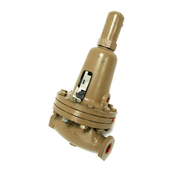
cashco 1000HP Посібник з монтажу, експлуатації та технічного обслуговування
Переглянути онлайн або завантажити pdf Посібник з монтажу, експлуатації та технічного обслуговування для Контролер cashco 1000HP. cashco 1000HP 17 сторінок. Cryogenic pressure reducing regulator
Також для cashco 1000HP: Інструкція з монтажу, експлуатації та технічного обслуговування (14 сторінок)

ISO Registered Company
MODEL 1000HP - DIFFERENTIAL
PRESSURE REDUCING REGULATOR
I. DESCRIPTION AND SCOPE
The Model 1000HP-1+6 and 1000HP-1+8 are dif fer en tial pressure reducing regulators used to control dif fer en tial
pressure between downstream (outlet or P
are 1/2" , 3/4", 1", 1-1/4", 1-1/2" and 2" (DN15, 20, 25, 32, 40 and 50). With proper trim uti li za tion and jet selection,
this unit is suitable for liquid, gaseous, or steam service. Refer to Technical Bulletin 1000HP-DIFF-TB for sizing,
application and selection rec om men da tions.
II. INSTALLATION
1. An inlet block valve should always be installed.
An outlet block valve is desirable.
2. A manual bypass valve is recommended for "hot
piping" systems to assist in piping warm-up at
startup.
3. An isolation valve on the loading line is not
rec om mend ed. The annular body ring of the
1000HP-1+8 may be piped to a safe drainage
point, but no valve should be installed in the drain
line.
4. Pipe unions must be installed to allow removal from
piping. Trim can only be changed by unit removal
from pipeline. If flanges are utilized, a lap joint
flange is required on the inlet end of the regulator
to help align bolt holes as the cylinder screws into
place. NOTE: Cashco does not rec om mend field
welding on the cylinder (inlet) end of the valve due
to the possibility of warpage.
DO NOT HYDROSTATIC TEST THROUGH AN
IN STALLED UNIT; ISOLATE FROM TEST. DO NOT
HY DRO STAT IC TEST THE LOADING PRESSURE
WITH OUT PRESSURE IN THE MAIN REGULATOR.
The name plate indicated outlet pressure rating, if
reached, may cause internal damage. Refer to Tech ni cal
Bulletin Model 1000HP-DIFF-TB, Table 3 for "emer gen cy
overpressure level" that will not do irreparable internals
damage. In addition, note on the name plate that the
Inlet and Outlet pressure and tem per a ture ratings are
at different levels.
INSTALLATION, OPERATION & MAINTENANCE MANUAL
) pressure and a loading (P
2
CAUTION
SECTION I
Load
SECTION II
Recommended Piping Schematic for
Differential Pressure Reducing Station
5. An outlet pressure gauge should be located
ap prox i mate ly ten pipe diameters downstream,
and within sight. A loading pressure (or differential
pressure) gauge is rec om mend ed.
6. All installations should include a downstream
re lief device if the inlet pressure could exceed the
pressure rating of any downstream equipment or
the maximum outlet pressure rating of the unit.
7. Clean the piping of all foreign material including
chips, welding scale, oil, grease and dirt
before in stall ing the regulator. Strainers are
rec om mend ed.
8. In placing thread sealant on pipe ends prior to
en gage ment, ensure that excess material is
re moved and not allowed to enter the regulator
upon startup.
9. Flow Direction: Install so the flow direction match es
the arrow cast on the body.
) pressure to the spring chamber. Sizes
IOM-1000HP-
Differential
01-17
