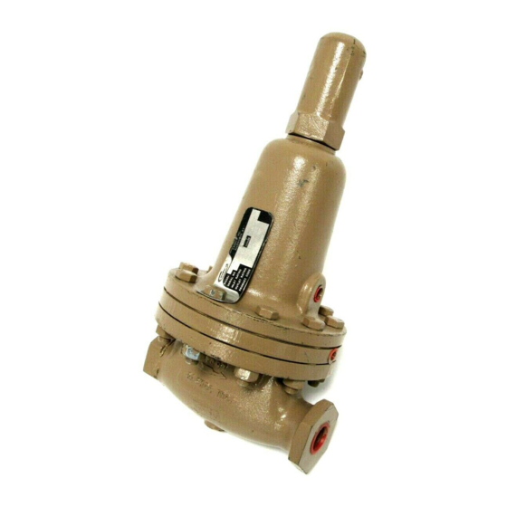
cashco 1000HP-5 Інструкція з монтажу, експлуатації та технічного обслуговування - Сторінка 5
Переглянути онлайн або завантажити pdf Інструкція з монтажу, експлуатації та технічного обслуговування для Контролер cashco 1000HP-5. cashco 1000HP-5 14 сторінок. Cryogenic pressure reducing regulator

15. Inspect pressure plate (3) to ensure no
de for ma tion due to over-pres sur iza tion.
If de formed, bent, or otherwise distorted,
re place.
16. Ensuring that the curved outer rim side
of the pressure plate (3) rests against the
dia phragm (20) directly, place the pressure
plate (3) over the pusher plate and stud (13).
Place nut (11) onto the stud (13) and tighten
to 35 ft.-lbs. torque for metal diaph ragm.
Use two flange bolts (8) to keep multiple
dia phragms' (20) bolt holes prop er ly aligned
while tightening the stud nut (10). (DO NOT
USE FINGERS TO HOLD DIAPHRAGMS
(20) DURING TIGHT EN ING OF NUT (11).)
17. Remove cotter pin (15) securing stud nut (10)
to lower end of pusher plate and stud (13), and
replace with a new pin (15). (Do not allow the
stud nut (10) to move when the cotter pin (15)
is removed.)
18. Remove rocker arm shaft (17) and rocker
arm (14). Measure inside of rocker arm (14)
"prongs" as indicated below:
Dim.
Mat'l
1/2"
3/4"
A
BR
7/8"
1-5/32"
B
BR
5/8"
25/32"
A
SST
13/16"
1-1/16"
B
SST
9/16"
23/32"
If either of the above dimensions are
ex ceeded by 1/8", re place rocker arm
(14).
IOM-1000HP-Cryogenic
Valve Size
1"
1-1/4"
1-1/2"
1-7/16"
1-13/16"
1-25/32"
2-3/16"
3/4"
29/32"
7/8"
29/32"
1-7/16"
1-1/2"
1-25/32"
2-5/32"
3/4"
11/16"
7/8"
29/32"
19. Check rocker arm shaft (17) for wear and
straightness. Replace if damaged. Rein stall
in body (1) through rocker arm (14). Apply
thread sealant to the rocker arm shaft (17)
threads prior to tightening. Make sure that the
rocker arm shaft (17) enters the support slot
op po site the threaded open ing, and does not
align crooked and restrained from full thread
engagement of the rocker arm shaft (17).
Make sure that the rocker arm (14) prongs that
straddle the piston (24) hold the piston collar
(23) against the piston (24); do not allow the
rocker arm (14) prongs to push directly on the
piston (24).
20. Clean the body (1) diaphragm flange. Seal ant
may be applied to the body (1) flange prior
to diaphragm (20) placement. Install a new
diaphragm gasket (19).
21. Using small gauge wire approximately 18"
long, form a hook, and place the hook over
one prong of the rocker arm (14), and rotate
the rocker arm (14) up until slack is re moved
in the mechanism. Secure the wire through a
body (1) flange bolt hole on the outlet side of
the regulator.
22. Take the diaphragm sub-assembly (Step 16)
and lower it down into the body (1) cavity
off-center approximately 3/4"-1" and to wards
the inlet side of the regulator. When fully
lowered, slide the diaphragm sub-as sem bly
horizontally towards the regulator's outlet.
The wire of Step 21 should hold the rocker
arm (14) up to allow engaging of the pusher
plate and stud (13) (with stud nut (10) and stud
collar (16)), so the rocker arm (14) prongs rest
directly on the stud collar (16). (Do not allow
the rocker arm (14) prongs to get between
the stud nut (10) and the stud collar (16).)
Pull firmly to remove wire holding rocker arm
(14) up.
23. Align diaphragm (20) bolt holes with body (1)
flange bolt holes. Set range spring (27) onto
pressure plate (3), place spring button (4) on
top of range spring (27). Place cryo gen ic,
multi-purpose temp erature lubricant into
2"
depression of spring button (4).
5
