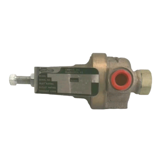
cashco 4381 Посібник з монтажу, експлуатації та технічного обслуговування
Переглянути онлайн або завантажити pdf Посібник з монтажу, експлуатації та технічного обслуговування для Контролер cashco 4381. cashco 4381 8 сторінок. Pressure reducing regulators
Також для cashco 4381: Посібник з монтажу, експлуатації та технічного обслуговування (10 сторінок)

MODELS 3381 AND 4381
I. DESCRIPTION AND SCOPE
Models 3381 and 4381 are pressure reducing regulators used to control downstream (outlet or P
Sizes are 1/4" and 3/8" (DN8 and DN10) for the 3381. Sizes for the 4381 are 1/4", 3/8", and 1/2" (DN8, DN10,
and DN15). The 3381 is a bronze bodied unit; the 4381 incorporates a stainless steel body. With proper trim
utilization, both units are suitable for liquid, gaseous and steam service (the 4381 can also be used with vari-
ous chemicals). Refer to Technical Bulletins 3381-TB and 4381-TB for specific design conditions and selection
recommendations.
The instructions in this manual will refer to both models, unless otherwise stated.
II. INSTALLATION
CAUTION
For welded installations, all internal trim parts, seals and
diaphragm(s) must be removed from regulator body prior
to welding into pipeline. The heat of fusion welding will
damage non-metallic parts if not removed. NOTE: This
does not apply to units equipped with extended pipe
nipples.
CAUTION
Option-1+6 contains single diaphragm construction. In
the event of diaphragm failure, the process fluid will mix
with the loading fluid. Please alert your representative so
an alternative product can be selected.
1. An inlet block valve should always be installed.
2. If service application is continuous such that
shutdown is not readily accomplished, it is rec-
ommended that an inlet block valve, outlet block
valve, and a manual bypass valve be installed.
3. Pipe unions should be installed to allow removal
from piping.
4. An outlet pressure gauge should be located ap-
proximately ten pipe diameters downstream, and
within sight.
5. All installations should include a downstream relief
device if the inlet pressure could exceed the pres-
sure rating of any downstream equip ment or the
maximum outlet pressure rating of the unit.
INSTALLATION, OPERATION & MAINTENANCE MANUAL (IOM)
PRESSURE REDUCING REGULATORS
SECTION I
SECTION II
CAUTION
Installation of adequate overpressure protection is recom-
mended to protect the regulator from overpressure and
all downstream equipment from damage in the event of
regulator failure.
6. Clean the piping of all foreign material including
chips, welding scale, oil, grease and dirt before
installing the regulator.
mended.
7. In placing thread sealant on pipe ends prior to
engagement, ensure that excess material is re-
moved and not allowed to enter the regulator upon
startup.
8. Flow Direction: Install so the flow direction match-
es the arrow cast on the main regulator body.
9. For best performance, install in well drained hori-
zontal pipe, properly trapped if a steam service
application.
IOM-3381/4381
11-08
) pressure.
2
Strainers are recom-
