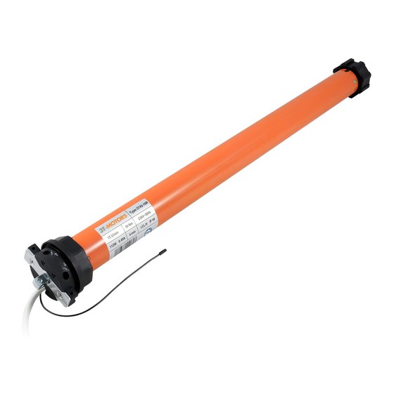
3T-Components 3T-MOTORS 3T35-10R Посібник з монтажу та експлуатації - Сторінка 10
Переглянути онлайн або завантажити pdf Посібник з монтажу та експлуатації для Двигун 3T-Components 3T-MOTORS 3T35-10R. 3T-Components 3T-MOTORS 3T35-10R 20 сторінок. Radio shutter / awning motors with mechanical limit switches
Також для 3T-Components 3T-MOTORS 3T35-10R: Посібник з монтажу та експлуатації (20 сторінок)

INSTALLATION INSTRUCTIONS
On the opposite side of the motor, push the roller capsule out of the roller shutter shaft until it fits into the ball bearing inserted in the wall bearing.
•
Fix roller capsule to roller shutter shaft with self-tapping screw. Position the screw at a punched hole. This prevents the screw from slipping.
•
Roller capsule
Shutter motor wiring:
7
Connect the radio roller shutter motor to the mains.
•
The electrical connection of the roller shutter motor and control unit may only be carried out by qualified personnel.
•
3) green/yellow = PE Protective conductor
Power grid
230 V / 50 Hz
Programming radio transmitter:
8
Pair radio transmitter to shutter motor. See Programming radio transmitter > Pairing handheld transmitter to 3T radio motor type R (page 16).
•
If the direction of rotation is reversed, please change it with the paired radio handheld transmitter > Change direction of rotation of radio motor (page 16).
•
Setting the end positions:
9
Explanation of the limit switch screws
There are 2 limit switch screws on the motor head. One limit switch screw is responsible for the upper end position, the other for the lower end position.
The end positions can be adjusted by turning the limit switch screws with the adjustment pin.
Motor type 3T45-R / Power cable to rear
1) brown / black = L1 / Phase
2) blue = N Neutral conductor
1 (L1)
2 (N)
3 (PE)
Motor type 3T45-R / Power cable to front
Wall bearing +
Ball bearing
1) brown / black = L1 / Phase
2) blue = N Neutral conductor
3) green/yellow = PE Protective conductor
Motor type 3T35-R / Power cable to rear
3T-MOTORS Radio tubular motors | Installation instructions
Shutter motor
1 (L1)
230 V / 50 Hz
2 (N)
3 (PE)
Adjustment pin
On 3T35-R motor types, the limit
switch screws are located on one
side of the motor head only.
10
