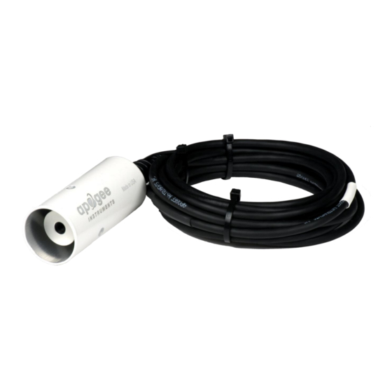
Apogee SI-431 Посібник користувача - Сторінка 18
Переглянути онлайн або завантажити pdf Посібник користувача для Вимірювальні прилади Apogee SI-431. Apogee SI-431 20 сторінок. Infrared radiometer
Також для Apogee SI-431: Посібник користувача (20 сторінок), Посібник користувача (20 сторінок)

TROUBLESHOOTING AND CUSTOMER SUPPORT
Independent Verification of Functionality:
The simplest way to check sensor functionality is the aM2! command. This command returns detector
temperature and detector voltage output. Detector temperature should read very near room
temperature. When the aperature of the sensor is covered with aluminum foil, the voltage output should
read very near 0 mV.
If the sensor does not communicate with the datalogger, use an ammeter to check the current drain. It
should be near 1.1 mA when the sensor is not communicating and spike to approximately 6 mA when the
sensor is communicating. Any current drain greater than 6 mA indicates a problem with power supply to
the sensors, wiring of the sensor, or sensor electronics.
Compatible Measurement Devices (Dataloggers/Controllers/Meters):
Any datalogger or meter with SDI-12 functionality that includes the M or C command.
An example datalogger program for Campbell Scientific dataloggers can be found on the Apogee
webpage at http://www.apogeeinstruments.com/content/Infrared-Radiometer-Digital.CR1.
Modifying Cable Length:
SDI-12 protocol limits cable length to 60 meters. For multiple sensors connected to the same data line,
the maximum is 600 meters of total cable (e.g., ten sensors with 60 meters of cable per sensor). See
Apogee webpage for details on how to extend sensor cable length
(http://www.apogeeinstruments.com/how-to-make-a-weatherproof-cable-splice/).
Signal Interference:
Due to the small voltage signals from the detector, care should be taken to provide appropriate
grounding for the sensor and cable shield wire, in order to minimize the influence of electromagnetic
interference (EMI). In instances where SI-100 series radiometers are being used in close proximity to
communications (near an antenna or antenna wiring), it may be necessary to alternate the data recording
and data transmitting functions (i.e., measurements should not be made when data are being transmitted
wirelessly). If EMI is suspected, place a tinfoil cap over the front of the sensor and monitor the signal
voltage from the detector. The signal voltage should remain stable at (or very near) zero.
18
