Appalachian Stove & Fabricators UV-EF-MIL 30-N Посібник з монтажу та експлуатації - Сторінка 7
Переглянути онлайн або завантажити pdf Посібник з монтажу та експлуатації для Внутрішній камін Appalachian Stove & Fabricators UV-EF-MIL 30-N. Appalachian Stove & Fabricators UV-EF-MIL 30-N 11 сторінок. Gas log heaters

Flame Check
A periodic visual check of the flames should be made. The pilot
flame should always be present when the appliance is in operation.
See figures D and E.
In normal operation (at a full rate for approximately 15 minutes),
the following flame appearances should be observed:
Rear flames: The flames at the rear or at either side of the top log
should be very similar, yellow in color, and should extend about three
to four inches above the large center log for natural gas, two to three
inches for Propane.
IMPORTANT: IF THESE FLAMES BECOME LARGER SEE
"CLEANING INSTRUCTIONS"
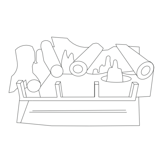
Main Burner: The flames at the burner front face will be blue
becoming yellowish as they hit the bottom of the front logs. Typical
main burner flame shapes are given in Figure E.
NOTE: For your safety, the appliance is equipped with an oxygen
depletion system. The system sensed the amount of oxygen in the
atmosphere and switches off the gas supply in case the level of
oxygen falls below a safe level.
WHEN USED AS A HEATING APPLIANCE/HEAT OUTPUT
The heat output is controlled by the span knob, or optional
thermostat, not by the main control knob. The span knob will adjust
flame intensity.
This appliance may be used as a heating appliance only if
unvented heating appliances are permitted by local state and city
codes.
PART NAME
1. Rear Log
2. Front Right Log
3. Front Left Log
4. Top Left Log
5. Top Mid Log
6. Top Right Log
7. Emberflame Glo Pad
8. Control Valve (N)
(Robert Shaw)
(Genesis)
(S.I.T.)
Control Valve(LP)
(Robert Shaw)
(Genesis)
(S.I.T.)
PART #
#REQ
24EF-021
24EF-022
24EF-023
24EF-024
24EF-025
24EF-026
24EF-027
24UV120
24UV120E
24UV140
24UV121
24UV121E
24UV141
Figure E
WARNING: Failure to keep the primary air
opening(s) of the burner(s) clean may
result in sooting and property damage.
PART NAME
1
9. Piezo
1
10. Pilot Assembly (N)
1
Pilot Assembly (P)
1
11. Rear Burner Orifice
1
12. Main Burner Orifice
1
13. Main Burner (N)
Main Burner (LP)
14. Main Burner Tube
1
15. Lava Rock Tray
1
1
1
Source on Page 10
1
1
PART #
#REQ
UV087
UV070N
UV071P
24UV010C (N)
24UV052 (N)
24UV4518-024
24UV4518-168
13971-016
13971-003
1
1
1
1
1
1
1
1
1
7
