Datakom DKG-117 Посібник користувача - Сторінка 7
Переглянути онлайн або завантажити pdf Посібник користувача для Реле Datakom DKG-117. Datakom DKG-117 12 сторінок. Synchroscope and check synch relay
Також для Datakom DKG-117: Посібник користувача (12 сторінок)

DKG-117 User Manual
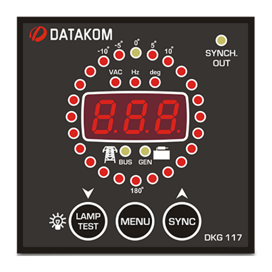
3.2 Digital Display
The unit has a three digit seven segment display. It shows:
-Measured parameters,
-Parameter names,
-Program parameters.
The navigation between different parameters is made with the MENU pushbutton. When the
MENU key is hold pressed, the parameter name will be displayed.
By pressing the MENU key, below values may be displayed:
-U1: busbar phase to neutral voltage
-U2 :genset phase to neutral voltage
-dU: voltage difference between busbar and genset phases
-F1: busbar frequency
-F2: genset frequency
-dF: frequency difference between busbar and genset
-deg: phase angle between busbar and genset phases (degrees)
4. OPERATION
The unit is designed for continuous operation from the genset battery voltage (12 or 24 volts DC). It
will shut-off its displays in 1 minute if there is no voltage at the AC inputs and if no key is pressed. It will power-
up automatically when voltage is applied to either genset or busbar voltage input or any front panel pushbutton
is depressed.
The synchroscope display will illuminate automatically if both genset and busbar phase voltages are
within their programmed limits. Otherwise the synchroscope will turn off to prevent the display of irrevelant
information.
The GEN led will turn off if the genset phase voltage is outside the set limits. It will flash when the
genset phase voltage is within the limits and the synchronization checking is disabled. It turns on steadily when
the synchronization checking is enabled. Please check the PROGRAMMING section for limit setting.
The BUS led will turn off if the busbar phase voltage is outside the set limits. It will turn on steadily if
the busbar phase voltage is within the limits. Please check the PROGRAMMING section for limit setting.
The synchronization checking is initiated either manually by depressing the SYNCH pushbutton or
with the SYNCHRONIZATION CHECK ENABLE signal input.
If the synchronization checking is enabled, the unit will be allowed to close the relay output when the
synchronization conditions are met. Otherwise it will not close the relay even if conditions are met. The
SYNCHRONIZATİON CHECK ENABLE signal input may be hard-wired to battery negative for the immediate
synchronization after genset runs. However a programmable pre-synchronization delay (P_08) may be
inserted with the programming menu in order to allow the genset to stabilize (or even to heat up if needed).
The synchronization checking is not timed. The unit will continue checking the synchronization until the
synchronization conditions are satisfied or the process terminated with the SYNCH key or the
SYNCHRONIZATION CHECK ENABLE signal.
A closed to open transition on the SYNCHRONIZATION CHECK ENABLE input will cause the
SYNCH RELAY to deenergize and the synchronization checking to terminate. The synch checking may also
be initiated or terminated manually by depressing the SYNCH pushbutton.
Once the SYNCH CHECK relay is energized, further synchronization checking may be enabled or
disabled following the value of the program parameter P_09. If the synchronization checking is disabled after
closing the SYNCH CHECK relay, the relay output will not deenergize even if the paralleling contactor fails to
close. It is the responsibility of the panel builder to use a quickly closing contactor.
V-01
(24.03.2014)
- 7 -
