Elsist SlimLine MPS055 00 Series Посібник з експлуатації обладнання - Сторінка 2
Переглянути онлайн або завантажити pdf Посібник з експлуатації обладнання для Блок управління Elsist SlimLine MPS055 00 Series. Elsist SlimLine MPS055 00 Series 2 сторінки. Raspberry pi cpu module
Connessioni
La CPU SlimLine Raspberry PI è dotata di morsetti estraibili
per la connessione dell'alimentazione e Bus di campo, connettore
IDC per il collegamento dei moduli di espansione, connettore RJ45
per il collegamento della porta Ethernet e di connettori USB-A per
la connesione delle porte USB Host.
Alimentazione (Fig. 8)
Il modulo deve essere alimentato con una tensione continua
nel range 10-30V. La connessione della alimentazione deve essere
effettuata in accordo alla Fig. 8.
La presenza della tensione di alimentazione è segnalata dal
LED verde "PWR".
ATTENZIONE! Il superamento del valore massimo di
!
tensione indicato può provocare il danneggiamento
irreversibile dell'apparato.
Collegamento di terra (Fig. 8)
Il dispositivo deve essere collegato direttamente a terra
mediante l'apposito morsetto del connettore di alimentazione (Fig.
8).
Il collegamento deve essere eseguito mediante una cordina
avente sezione di almeno 1.5mm
2
, ad una barra equipotenziale di
rame di adeguata sezione.
Al fine di garantire una buona rejezione ai disturbi, è
necessario che questo collegamento sia mantenuto il più corto
possibile e non venga fatto passare con altri cavi.
Bus di espansione e 1-Wire (Fig. 9)
Il bus di comunicazione con i moduli di espansione sfrutta
2
TM
l'interfaccia I
C
ed è disponibile su connettore P7. I moduli di
espansione devono essere collegati in cascata tramite gli appositi
cavetti CBL074*000 e/o CBL045*000 (da ordinare separatamente).
In Fig. 10 è schematizzato il collegamento dei moduli di
espansione.
Al modulo CPU possono essere collegati fino a 8 moduli di
espansione (previa verifica assorbimenti massimi).
ATTENZIONE! Prima di collegare al modulo CPU i
!
moduli di espansione, accertarsi che questo non sia
alimentato. In caso contrario i dispositivi potrebbero
essere irrimediabilmente danneggiati.
Il dispositivo è dotato di bus 1-Wire
TM
(P11), attraverso il quale
è possibile l'acquisizione di dispositivi i-Button
TM
, quali TAG di
identificazione personale, sensori di temperatura e molto altro.
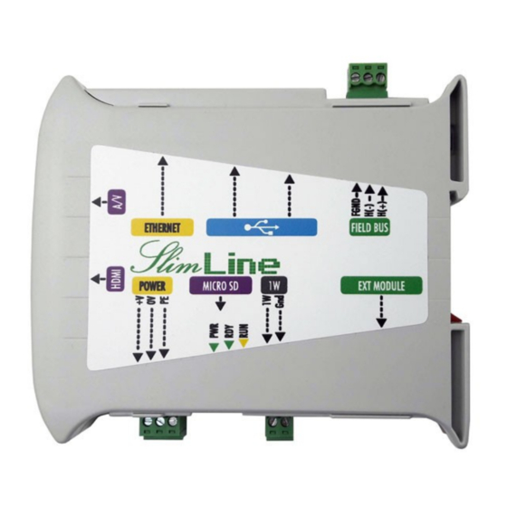
Connections
The SlimLine Cortex M7 (LogicLab) CPU module is provided of
extractable TB to connect Power and Field bus, IDC connector to
connect the extension modules, RJ45 connector to connect
Ethernet port, and 4 USB-A connector USB host.
Power supply (Fig. 3)
The module can be powered with a DC source within the range
10-30Vdc. The power connection must be done according to the
Fig. 8.
The power is signalized by the green LED "PWR".
WARNING! Values greater than the maximum allowed
!
may damage the device seriously.
Ground connection (Fig. 8)
The device must be connected directly to Ground using the
terminal block on the power supply connector (Fig. 8).
The connection must be performed through a wire with section
at least of 1.5mm
2
, to a copper equipotential bar of adequate
section.
To guarantee a good noise rejection, keep this connection as
short as possible and take care to place it far away to the other
cables.
Extension bus and 1-wire bus (Fig. 9)
The communication bus with the extension modules uses the
Fast I
2
C™ interface and it's available on the IDC10 connector (P7).
The extension modules must be cascade connected through the
special cables CBL074*000 and/or CBL045*000 (to be ordered
separately).
The Fig. 9 in an example of extension modules connection.
Up to 8 extension modules may be connected to the CPU.
(after checking the maximum current needed)
WARNING! Before to connect the extension modules
!
to the system, be sure that it's powered off. Missing
this rule may produce failures in the modules.
The device is equipped with a 1-Wire
TM
bus (P11), through it
you can acquire i-Button
TM
devices, such as TAG for personal
identification, temperature sensors and other devices.
Bus di campo (Fig. 4)
Il modulo può essere dotato di bus di campo RS485 o CAN
Bus (vedi identificazione prodotto Fig. 7), isolato galvanicamente
dal sistema. Per il collegamento del bus attenersi alla figura a lato.
Attraverso il jumper LK1 può essere inserita la resistenza di
terminazione 120Ohm o meno.
Porta Ethernet (Fig. 1)
Il modulo può essere dotato di una porta ethernet disponibile
sul connettore RJ45; le connessioni, evidenziate in Fig. 1, sono
compatibili con lo standard ethernet IEEE 802.3 10/100/1000base-T
(x). Per l'inserimento in una rete ethernet devono essere utilizzati
cavi UTP Cat. 5 RJ45 ed uno switch, mentre, per un collegamento
punto-punto, è sufficiente utilizzare un cavo patch RJ45 senza
utilizzo di altri dispositivi. Il dispositivo è dotato di Auto-MDIX, quindi
non è necessario disporre di cavo cross per il collegamento diretto
a PC.
Sul connettore ethernet sono disponibili due LED di
segnalazione dello stato della connessione:
Il LED Verde segnala, quando acceso, che la rete sta
funzionando a 100Mb/s.
Il LED Giallo segnala, quando acceso, che la rete sta
funzionando a 1Gb/s.
Il modulo viene fornito con DHCP abilitato.
Porte USB Host (Fig. 2)
Il modulo è dotato di 4 porte USB-A Host. Possono essere
collegati a queste porte dispositivi quali pen drive, stampanti,
modem ecc.. Il modulo è in grado di fornire l'alimentazione al
dispositivo esterno (5V 100mA max. per ogni porta).
Slot SD Card (Fig. 8)
Il modulo è dotato di uno slot micro-SD Card. La card può
essere utilizzata sia per funzioni di archiviazione del programma
utente, che per funzioni di storicizzazione dati durante il
funzionamento.
Segnalazioni stato (Fig. 6)
Il modulo è dotato di LED per la segnalazione dello stato di
funzionamento, in particolare è segnalato lo stato di:
PWR (LED Verde)
·
Indica la presenza dell'alimentazione
RUN (LED Giallo)
·
Lampeggiante regolare indica che il sistema è in funzione,
RDY (LED Verde)
·
Acceso indica che il sistema è pronto e gestisce i moduli I/
O. La mancanza di RDY resetta lo stato delle uscite dei
moduli di espansione eventualmente connessi al sistema.
Field bus (Fig. 4)
The module may be provided of a RS485 or CAN field bus (see
product identification Fig. 7), in both cases the bus is galvanically
insulated from the system. To connect the field bus please see
Figure on side.
Through the LK1 jumper may be connected or not the 120
Ohm termination resistor.
Ethernet port (Fig. 1)
The module may be provided of an RJ45 connector; the
connection, shown in Fig. 1, are compatible with the standard
Ethernet IEEE 802.3 10/100/100-Base T.
To connect the device in an Ethernet network must be used
UTP Cat. 5 cables RJ45, connected to an HUB or a switch, while to
made a point to point connection it's enough to use an RJ45 patch
cable without HUBs. The device is Auto-MDIX, so no cross cable is
needed to connect it to a PC directly.
On ethernet connector are available two LED for connection status
signaling:
The green LED signals, when on, that the network is running at
10/100Mb/s speed.
The yellow LED signals, when on, that the network is running at
1Gb/s speed.
The module is factory with DHCP enabled.
USB Host port (Fig. 2)
The module is equipped with 4-port USB-A able to be used as
host mode. Can be be connected to this port devices such as pen
drives, printers, modems etc.. The module is capable of providing
power to the external device (5V 100mA max.).
Slot SD Card (Fig. 8)
The module may be provided of a slot mini-SD Card. The card
may be used for archive functions or for data history functions
during normal running.
Status signaling (Fig. 6)
The device is provided of some LEDs to signal its status,
particularly is signaled:
PWR (Green LED)
·
Indicates that device is powered
RUN (Yellow LED)
·
Regularly blinking indicates that the system is running,
RDY (Green LED)
·
2
TM
I
C
è un marchio registrato di NXP Semiconductors
1-Wire
®
è un marchio registrato di Maxim/ Dallas Semiconductor
When light indicates that the system is ready and it
manages the I/O modules according to the user program.
When it's off it resets the output status on extension
modules eventually connected to the system.
2
TM
I
C
is a trade mark of NXP Semiconductors
1-Wire
®
protocol is a registered trade mark of Maxim/ Dallas Semiconductor
Technical Specifications
Device Code
MPS055*000
Power Supply
10-30Vdc 3W (1)
Power to exp. bus
Processor
Broadcom BCM2837B0, Cortex-A53 64-bit SoC @ 1.4GHz max
Memory
Mass memory
On micro-SD card slot (MicroSD-CARD 8GB HC provided)
File system
FTP server
Yes, off-system operation with lithium battery (5 years min.)
Real Time Clock
SNTP (Simple Network Time Protocol) supported
USB I/F
4 USB-A ports (host mode) 2.0 USB compatible (5V 100mA/port max.)
1-Wire I/F
Ethernet I/F
RJ45 10/100/1000base-T (x) Auto-MDIX (300Mbps max supported)
WiFi I/F
2.4GHz and 5GHz compatible 802.11b/g/n/ac
Bluetooth I/F
Bluetooth 4.2, Bluetooth Low Energy (BLE)
HDMI I/F
Composite video I/F
1 stereo out + composite video
Insulated Fail Safe High impedance
Field bus
none
Expansion bus
Expansion modules
8 max. (to be verified according to the connected module)
Status indicators
User configurable web
pages
Operating temperature: from -0 to +50°C
Environment
Storage temperature: from -40° to +80°C
Relative Humidity: Max. 90%
Dimensions: 22.5 mm L x 101 mm W x 120 mm H
Dimensions and weight
Approvals
Notes
Collegamento Bus di campo
Field bus connection
Collegamento Half-Duplex (solo RS485)
Half-Duplex connection (RS485 only)
•
La distanza massima tra il primo e l'ultimo dei
dispositivi non deve superare i 1200 mt (RS485)
•
La resistenza di terminazione deve essere sempre
inserita sul primo e sull'ultimo dei dispositivi.
•
Il cavo deve essere schermato e twistato.
Note tecniche per connessione CAN
Technical notes for CAN connection
Le specifiche del Bus CAN sono regolate dalla norma ISO
11898. La velocità max di trasmissione è pari ad 1Mbit/s riferita ad
11898 Standard. The maximum bus speed is 1Mbit/s for a cable
un cavo di lunghezza max. 40mt. Nella tabella sotto sono riportate
length of 130ft. In the table below are listed the allowed speed
le velocità max in funzione della lunghezza del cavo.
function of cable length.
Massima velocità in funzione della lunghezza bus (CAN)
Max speed function of bus length (CAN)
Lunghezza del bus
Velocità trasmissione
Bus Length
Transmission speed
100 meters (330 ft)
500 kbit/s
500 meters (1600 ft)
200 meters (650 ft)
250 kbit/s
6 kilometers (20000 ft)
Schema di connessione
Drawing connection
3
1
3
1
P1
P1
LK1
LK1
MPS055*100
MPS054*200
10-30Vdc 3,3W (1)
5Vdc 2A max.
1GB LPDDR2 SDRAM
Raspbian Standard
Yes
1
1 Full size
Insulated CAN Bus 2.0B compatible,
RS485
ISO11898-1
I
2
C™
Power, RUN, READY
Yes (responsive)
Weight: 160g
CE, RoHS
(1) Worst case
•
The maximum distance between the first and the last
device does not exceed 4000 feet (RS485).
•
The termination resistor must be always connected on
the first and on the last device.
•
The cable must be shielded and twisted paired.
The technical specification for CAN bus are given by the ISO
Lunghezza del bus
Velocità trasmissione
Bus Length
Transmission speed
125 kbit/s
10 kbit/s
3
1
P1
LK1