elsner elektronik Cala KNX M1-T Посібник із швидкого старту - Сторінка 2
Переглянути онлайн або завантажити pdf Посібник із швидкого старту для Перемикач elsner elektronik Cala KNX M1-T. elsner elektronik Cala KNX M1-T 2 сторінки. Push button with temperature sensor
Також для elsner elektronik Cala KNX M1-T: Посібник із швидкого старту (2 сторінок)

Fig. 2: Sectional drawing.
The Cala KNX M-T push button fits in a stan-
dard connector socket (Ø 60 mm, depth 42 mm).
The frame is not included in the delivery!
Installation depth
27 mm
Construction depth
10 mm
May be installed and operated in dry interior rooms only.
When selecting an installation location, ensure that the measurement results are af-
fected as little as possible by external influences. Possible sources of interference
include:
•
Direct sunlight
•
Drafts from windows and doors
•
Draft from ducts which lead from other rooms or from the outside to the
junction box in which the sensor is mounted
•
Warming or cooling of the building structure on which the sensor is mounted,
e.g. due to sunlight, heating or cold water pipes
•
Connection lines and ducts which lead from warmer or colder areas to the
sensor
Measurement variations from permanent sources of interference can be corrected
in the ETS in order to ensure the specified accuracy of the sensor (offset).
2.2. Device structure
2.2.1. Casing
1
2
1
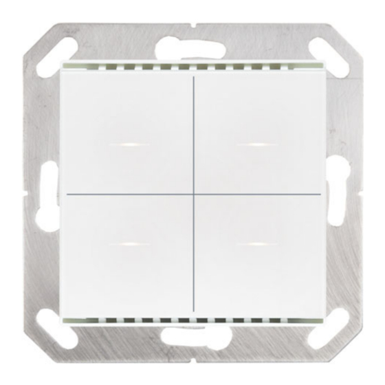
Fig. 3: Front
1 Ventilation slit (top and bottom)
2 Touch areas with LEDs
2
1
3
4
2.3. Installation of the sensor
First install the windproof socket with feed line. Seal the inlet tubes as well, in order
to prevent draughts.
Then screw the base plate to the socket and place the switch program frame. Con-
nect the bus cable +/- to the plug (black-red).
Insert the device firmly onto the metal frame using the catches so that the device
and the housing are fixed together. The device has to be inserted such that the bus
terminal faces up (see Fig. 4). This is necessary for a correct temperature measure-
ment and for Cala KNX M2-T and Cala KNX M4-T also for button allocation.
3.
Commissioning
Never expose the device to water (e.g. rain) or dust. This can damage the electro-
nics. You must not exceed a relative humidity of 95%. Avoid condensation.
After the bus voltage has been applied, the device will enter an initialisation phase
lasting a few seconds. During this phase no information can be received or sent via
the bus.
3.1. Addressing of the device at the bus
The individual address is assigned via the ETS. A button and a control LED are loca-
ted on the unit for this purpose (Fig. 4, No. 3+4).
The equipment is delivered with the bus address 15.15.255. Another address can be
programmed using the ETS.
When programming mode is active, the programming LED lights up and all other
LEDs also flash.
4.
Maintenance
Ventilation slits must not be dirty of covered. As a rule, it is sufficient to wipe the
device with a soft, dry cloth as required.
Cala KNX M-T push button • Version: 07.06.2022 • from version 0.1.4 • Technical changes and errors excepted. • Elsner Elektronik GmbH • Sohlengrund 16 • 75395 Ostelsheim • Germany • www.elsner-elektronik.de • Technical Service: +49 (0) 7033 / 30945-250
Cala KNX M-T push button
2
2
2
Fig. 4: Back
1 Base frame
2 KNX terminal BUS +/-
3 Programming button (reces-
5
sed) for teaching the device
4 Programming LED (recessed)
5 Catches
5.
Disposal
After use, the device must be disposed of in accordance with the legal regulations.
Do not dispose of it with the household waste!
1
2
2
1
2
