GAC ESD5151 Посібник із швидкого старту - Сторінка 2
Переглянути онлайн або завантажити pdf Посібник із швидкого старту для Блок управління GAC ESD5151. GAC ESD5151 6 сторінок. Speed control unit
Speed Droop Operation
Droop is typically used for the paralleling of engine driven
generators.
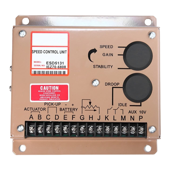
Place the optional external selector switch in the DROOP
position. DROOP is increased by clockwise rotation of the
DROOP adjustment control. When in droop operation, the
engine speed will decrease as engine load increases. The
percentage of droop is based on the actuator current change
from engine no load to full load. A wide range droop is avail-
able with the internal control. Droop level requirements
above 10% are unusual.
If droop levels experienced are higher or lower then these
required, contact the GAC for assistance.
After the droop level has been adjusted, the rated engine
speed setting may need to be reset. Check the engine speed
and adjust that speed setting accordingly.
Accessory Input
The Auxiliary Terminal N accepts input signals from load
sharing units, auto synchronizers, and other governor sys-
tem accessories, GAC accessories are directly connected to
this terminal. It is recommended that this connection from
accessories be shielded, as it is a sensitive input terminal.
If the auto synchronizer is used alone, not in conjunction with
a load-sharing module, a 3 M ohm resistor should be con-
nected between Terminals N and P. This is required to match
the voltage levels between the speed control unit and the
synchronizer.
When an accessory is connected to Terminal N, the speed
will decrease and the speed adjustment must be reset.
When operating in the upper end of the control unit frequen-
cy range, a jumper wire or frequency trim control may be
required between Terminals G and J. This increases the fre-
quency range of the speed control to over 7000 Hz.
Accessory Supply
The +10 volt regulated supply, Terminal P, can be utilized
to provide power to GAC governor system accessories. Up
to 20 ma of current can be drawn from this supply. Ground
reference is Terminal G.
Wide Range Remote Variable Speed Operation
Simple and effective remote variable speed can be obtained
with the ESD5100 Series speed control unit.
A single remote speed adjustment potentiometer can be
used to adjust the engine speed continuously over a specific
speed range. Select the desired speed range and corre-
sponding potentiometer value. (Refer to TABLE 1.) If the
exact range cannot be found, select the next higher range
potentiometer. An additional fixed resistor may be placed
across the potentiometer to obtain the exact desired range.
Connect the speed range potentiometer as shown in Dia-
gram 1
To maintain engine stability at the minimum speed setting, a
This document is subject to change without notice.
Caution: None of GAC products are flight certified controls including this item.
small amount of droop can be added using the DROOP ad-
justment. At the maximum speed setting the governor per-
formance will be near isochronous, regardless of the droop
adjustment setting.
Contact GAC for assistance if difficulty is experienced in ob-
taining the desired variable speed governing performance.
TAblE 1 VARIAblE RANGE pOTENTIOMETER VAlUE
SpeeD RAnge
900 Hz
2,400 Hz
3,000 Hz
3,500 Hz
3,700 Hz
DIAGRAM 1 pOTENTIOMETER WIRING
G
*Select proper potentiometer value from Table 1
SYSTEM TROUblEShOOTING
Insufficient Magnetic Speed Signal
A strong magnetic speed sensor signal will eliminate the
possibility of missed or extra pulses. The speed control unit
will govern well with 0.5 volts RMS speed sensor signal. A
speed sensor signal of 3 volts RMS or greater at governed
speed is recommended. Measurement of the signal is made
at Terminals C and D.
The amplitude of the speed sensor signal can be raised
by reducing the gap between the speed sensor tip and the
engine ring gear. The gap should not be any smaller than
0.020 in (0.45 mm). When the engine is stopped, back the
speed sensor out by 3/4 turn after touching the ring gear
tooth to achieve a satisfactory air gap.
Electromagnetic Compatibility (EMC)
EMI SUSCEPTIBILITY - The governor system can be ad-
versely affected by large interfering signals that are conduct-
ed through the cabling or through direct radiation into the
control circuits.
All GAC speed control sensors contain filters and shielding
designed to protect the unit's sensitive circuits from moder-
ate external interfering sources.
2
potentiometeR VAlue
1 K
5 K
10 K
25 K
50 K
J
K
L
*
cw
PIB1000 C