GAC ESD5200 Series Посібник - Сторінка 5
Переглянути онлайн або завантажити pdf Посібник для Блок управління GAC ESD5200 Series. GAC ESD5200 Series 7 сторінок. Speed control unit
9
ADDITIONAl FEATURES & OPTIONAl WIRINg
IDLe SPeeD SeTTInG
1.
Adjust the SPEED setting.
2.
After the control units speed setting had been adjusted, place the optional external selector
switch in the IDLE position.
3.
Increase the idle speed set point is increased by the clockwise rotation of the IDLE adjustment
control.
4.
When the engine is at idle speed, the speed control unit applies droop to the governor system
to ensure stable operation.
DrooP oPeraTIon
Droop is typically used for the paralleling engine driven generators. When in droop operation, the engine speed will decrease as engine
load increases. The percentage of droop is based on the actuator current change from no engine load to full load.
1.
Place the optional external selector switch in the DROOP position. DROOP is increased by clockwise rotation of the DROOP
adjustment control.
2.
After the droop level has been adjusted, the rated engine speed setting may need to be reset. Check the engines speed and adjust
that speed setting accordingly.
Though a wide range of droop is available with the internal control, droop level requirements of 10% are unusual. If droop
noTe
levels experienced are higher or lower than those required, contact GAC for assistance.
InTernaL SPeeD SwITcH
To set the overspeed function to approximately 10% above the requested speed.
1.
When the engine is running at the desired speed, push and hold the TEST button.
2.
While holding the TEST button, rotate the OVERSPEED adjustment counterclockwise
until the LED lights and the relay re-energizes
3.
Release the TEST button. Current to the actuator will be removed and the engine will
shut off.
4.
After the engine stops, press the RESET button or remove battery power.
5.
Restart the engine. It will return to the original speed setting.
Always use the relay contacts provided to shut down the system by a means
other than the governor or actuator. The overspeed protection system should
noTe
be tested and verified during scheduled service of equipment.
acceSSorY InPUT
Auxiliary Terminal N accepts input signals from load sharing units, auto synchronizers, and other governor system accessories. GAC ac-
cessories are directly connected to this terminal. Terminal N connections must be shielded.
When an accessory is connected to Terminal N, the speed will decrease and the speed adjustment must be reset.
When operating in the upper end of the control unit frequency range, a jumper wire or frequency trim control may be required between
Terminals G and J. This increases the frequency range of the speed control to over 7000 Hz (4200 RPM).
If the auto synchronizer is used alone, not in conjunction with a load sharing module, a 3 Ω resister should be connected between
noTe
Terminals N and P. This is required to match the voltage levels between the speed control unit and the synchronizer.
acceSSorY SUPPLY
Terminal P supplies +10 volt regulated supply to provide power to GAC governor system accessories. Up to 20 mA of current can be drawn
from this supply. Ground reference is Terminal G.
A short circuit on Terminal P can damage the speed control unit.
GAIN
5
ESD5200 Series Speed Control Unit 1-2021-C3 PIB1030
Governors America Corp. © 2021 Copyright All Rights Reserved
DEAD TIME
COMPENSATION POSTS
E2 E3
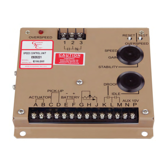
DROOP
IDLE
RESET TEST
OVERSPEED
ON
1
2
STABILITY