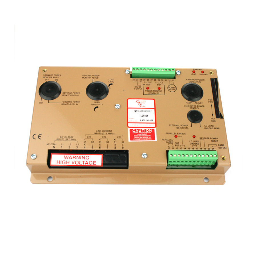
GAC LSM201N Посібник - Сторінка 9
Переглянути онлайн або завантажити pdf Посібник для Контролер GAC LSM201N. GAC LSM201N 11 сторінок. Load sharing modules

7
ADvANCED ADjUSTMENTS
lOAD SHARiNG ADjUStMENt
When proper phasing has been confirmed, the generators can be synchronized and paralleled. With the system paralleled and oper-
ating with no load, adjust each governor's speed trim for zero real power as indicated on each generator set's hertz-meter.
The system should be stable and no significant power from either generator should be indicated. If the system does not seem stable,
adjust each of the LOAD SENSITIVITY controls CCW about 1/3 of a turn or until the system is stable. If the sensitivity is set below 40
%, refer to System Troubleshooting section.
Electrical load can now be applied to the system.
All generator sets in the system should be sharing the systems load nearly proportionally. The generator set carrying the least
amount of load should be adjusted to accept more of the total system load. Turn the LOAD SENSITIVITY control adjustment CCW
on this unit to increase its load contribution.
lOAD ANtiCiPAtiON ADjUStMENt
The LOAD ANTICIPATION adjustment is factory set to zero sensitivity. To improve the genset's transient response, gradually
advance the adjustment CW to about 50 % while the generator sets are in parallel. The transient response improvement can be ob-
served when the engine load is changed. An optimum setting requires a speed recorder to minimize the transient in both magnitude
and duration. Instability may result it the adjustment is advanced too far CW.
REvERSE POWER ADjUStMENt
With the reset switch or jumper across Terminals 18 and 19, the reverse power monitor can be calibrated. To obtain reverse power
on a generator may be difficult. An alternate method is to simulate reverse power by reversing all the CTs temporarily when the unit
is in single unit operation.
NOTE: No serviceable points, parts or adjustments internally.
With the CTs still reversed, adjust the monitor's setting from 20 to 100 and the DELAY to fastest (full CCW). Apply a small amount of
load representing the trip point of the reverse power monitor, approximately 10 %. Turn the REVERSE POWER MONITOR adjustment
from 100 slowly toward 0 until the monitor turns on. Remove the generator load. The monitor should turn OFF (reset). Recheck the
setting by applying the 10% load again.
The Reverse Power Delay may now be set by turning this adjustment CW. The minimum delay necessary should be used, otherwise
leave this setting to full CCW (minimum delay).
NOtE: The delays are of the inverse time type. See previous description for details. Be sure to reinstate the CT connections
to their proper polarity before attempting parallel operation.
POWER RAMP DEFEAt - OPtiONAl
When in parallel with the mains under power control, if the mains fail the LSM200 Series load sharing module must revert to isochro-
nous load sharing quickly. The connection across the parallel cable (Terminals 10 and 11) must be opened and the mains load sharing
reduced to zero quickly (Terminals 15 to 16 connection). Defeating the mains ramp using a connection from Terminal 20 to 21. See
Section 5 Wiring diagram.
If the generator power control function is not used, adjust the RAMP and ADJUST to their 0 settings.
POWER MEtER OPERAtiON
The analog power output voltage signal is a good measure of engine power when the AC voltage from the generator is considered
to be constant. The external power meter can be any analog or digital meter with a relatively high input impedance (>10 K Ω) that is
within the voltage range of the unit. The (+) signal output is at Terminal 32 and the reference is at Terminal 33(-). Terminal 33 is refer-
enced at a voltage of 2.0 V DC above battery minus. Limit Terminal 32 to 10 ma.
The maximum range of voltage is -2 to +5 V DC across these two terminals. The bipolar output allows reverse power as well as
forward power to be detected. The EXTERNAL POWER METER CAL adjustment (-1 to % V DC) allows this signal to be adjusted for
lower levels to match the external instruments. CCW adjustment reduces the voltage range. Proportional to the CT current an output
of 5V indicates 5 A CT power (forward), and -1V indicates 1 A (reverse).
The internal bar graph is taken from the same voltage source. The bar graph can be calibrated for generator power output. The third
dot is zero power output and the 10th dot is 100% output. After full power has been applied to the generator, adjust the GENERATOR
POWER DISPLAY CAL for a full scale reading. Be sure the adjustment is made by turning the adjustment CW from the zero position.
LSM200 Series Load Sharing Modules 6-2021-B1 PIB4100
9
Governors America Corp. © 2021 Copyright All Rights Reserved
