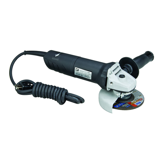
Dynabrade 40260 Інструкція з експлуатації - Сторінка 4
Переглянути онлайн або завантажити pdf Інструкція з експлуатації для М'ясорубка Dynabrade 40260. Dynabrade 40260 4 сторінки. Electric depressed center wheel grinder

Recommended Diameter of Accessories:
1. The tool can use 4-1/2" Type 27 Wheel accessories.
Mounting of Type 27 Wheel:
1. See instructions below.
Proper Support for the Workplace:
1. Insure that the workpiece is fixed so that it cannot become a projectile.
Right Angle Depressed Center Wheel Grinder – Is a right angle rotary electric hand tool with a 5/8"-11 spindle which includes: a lock-on on/off switch; side handle; a 4-1/2" guard;
and is equipped with an 8 ft. cord set.
1. With power source disconnected from tool, securely fasten abrasive/accessory on tool. The rated RPM of the accessory must be equal to or greater than the rated
RPM of the tool.
2. Hold tool by the motor housing and the side handle. Do Not hold tool by head/housing assembly. Keep hands away from all moving parts.
Important: A preventative maintenance program is recommended whenever portable power tools are used.
• Use only genuine Dynabrade replacement parts to insure quality. To order replacement parts, specify Model #, Serial # and RPM of your tool.
Routine Preventative Maintenance:
• Mineral spirits are recommended when cleaning. Do not use on electrical components or clean tool or parts with any solvents or oils containing acids, esters, ketones, chlorinat-
ed hydrocarbons or nitro carbons. Compressed air may be used to remove dirt from electrical components.
• DO NOT clean or maintain tools with chemicals that have a low flash point (example: WD-40
• Tool labels must be kept legible at all times, if not, reorder label(s) and replace. User is responsible for maintaining specification information i.e.: Model #, S/N, and RPM. (See
Assembly Breakdown)
• Visually inspect plugs and cords for frays, visible damage and signs of deterioration. Damaged or worn components must be replaced by Dynabrade to avoid a safety hazard.
• Brush Changing – Unplug tool, remove rear housing and brushes. Install new brushes, and replace rear housing. Run tool for 20 minutes at free speed to seat brushes.
Change brushes every 100 hrs. to ensure proper tool function. After changing brushes it is recommended to replace the right angle gear grease with 95542 Grease.
• After maintenance is performed on tool check for excessive tool vibration.
• Check for excessive current leakage at 550 volts with a current leakage checker on all screws and the gear case, if the electrical components have been
disturbed during repair.
Handling and Storage of Tool and Accessories:
• Store accessories in protective racks or compartments to prevent damage.
• Protect abrasive accessories from exposure to water, solvents, high humidity, freezing temperature and extreme temperature changes.
Type 27 Flanged Wheel (7/8" Dia. Arbor Hole)
1. With power source disconnected from the tool.
2. Clean spindle and flange mounting surfaces. Inspect for nicks, cuts and sharp edges.
3. Install drive flange with raised boss facing outward. Engage bottom flange slot and spindle flats.
4. Check for flange flatness and runout by rotating spindle and drive flange together.
5. Install Type 27 grinding wheel over spindle thread and over raised boss on flange.
6. With 1/4" thick wheels & greater, install outer flange nut with raised boss facing toward abrasive wheel,
engage spindle lock and secure flange firmly against wheel. (See fig. 1)
7. With 1/8" thick wheels & less, install outer flange nut with raised boss facing away from abrasive wheel,
engage spindle lock and secure flange firmly against wheel. (See fig. 2)
8. Check for wheel firmness by holding the spindle and pulling on the edge of the wheel in the
tightening direction.
Caution: Over tightening the outer flange nut can cause damage to the wheel and/or flanges.
• Use only Dynabrade 40720 Wheel Lock Nut & 40721 Flange.
Type 27 Hubbed Wheel (5/8"-11 Internal Affixed Flange)
1. With power source disconnected from the tool.
2. Some TYPE 27 grinding wheels come equipped with a disposable flange affixed to them. For use of this
type wheel store both the driving flange and the outer flange nut provided with the tool for future use.
3. Engage spindle lock and thread grinding wheel to tool securely.
4. Visually inspect the grinding surface face relationship to the bend of the lip on the guard.
5. ONLY USE grinding wheel whose face of the wheel is behind bend of lip on guard. (See fig. 3)
FIND THE MOST CURRENT OFFERING OF ACCESSORIES
AND SUPPORT DOCUMENTS @ WWW.DYNABRADE.COM
Reference Contact Information
1. CSA International
8501 East Pleasant Valley Road
Cleveland, Ohio 4431-5575
Tel: 1 (216) 524-4990
Fax: 1 (216) 642-3463
Visit Our Web Site: www.dynabrade.com
DYNABRADE, INC., 8989 Sheridan Drive • Clarence, NY 14031-1490 • Phone: (716) 631-0100 • Fax: 716-631-2073 • International Fax: 716-631-2524
© DYNABRADE, INC., 2010
TOOL DESCRIPTION
ASSEMBLY and OPERATION INSTRUCTIONS
MAINTENANCE and ACCESSORY CARE INSTRUCTIONS
Wheel Mounting Instructions
2. Government Printing Office – GPO
Superintendent of Documents
Attn. New Orders
P.O. Box 371954
Pittsburgh, PA 15250-7954
Tel: 1 (202) 512-1803
PRINTED IN USA
®
).
Side View
Right Angle Housing
Driving Flange
Spindle
Outer Flange Nut
Fig. 1
1/4"
Outer Flange Nut
Fig. 3
Side View
Right Angle Housing
Face of Wheel must be behind bend of lip.
Email: [email protected]
Safety Guard
Wheel
Fig. 2
1/8"
Outer Flange Nut
Safety Guard
Wheel
Bend of Lip
DYNABRADE
PD10.41_12/10
®
