Hi-Velocity RPM-E-70 Посібник з монтажу - Сторінка 5
Переглянути онлайн або завантажити pdf Посібник з монтажу для Охолоджувальні ящики Hi-Velocity RPM-E-70. Hi-Velocity RPM-E-70 6 сторінок.
Charging Cont'd
Most system start ups require only an adjustment to the
refrigerant level of the system. Should further refinement be
required, the TXV may be adjusted. A clockwise turn of the
superheat valve (the direction in which the cap is screwed on)
will result in a closing of the valve while a counterclockwise
turn (the direction in which the cap was unscrewed) will result
in opening of the valve. Always note system conditions before
adjusting the valve and allow 5 minutes for the system to settle
before making any further adjustments. Never adjust the TXV
more than one quarter turn at a time.
The RPM-E coil can operate at a level that is different from
most other conventional system coils. Typically, superheat level
are low, two to four degrees of superheat. Adjustment of the valve
also differs somewhat. Rather than having a large effect on the
range of superheat, adjustment of the valve has a larger effect
on the system pressures; superheat maintaining a fairly constant
point. Opening the valve will increase suction pressures and
decrease liquid pressures, while closing the valve will decrease
suction pressures and raise liquid pressures.
Heat Pumps
Traditionally, SDHV systems have been charged to special
guidelines when used in conjunction with heat pumps. This
charging procedure involved charging the units to normal
cooling capacities and reviewing the operation in heating mode.
If head pressures were found to be impinging on the high head
pressure limits, a small amount of refrigerant was removed to
prevent the unit from shutting down. The cause of high head
pressures in heating mode is due to the disparity in sizes of the
indoor and outdoor coils, along with the lower airflow rates of
SDHV systems.
With the introduction of newer, larger heat pumps, this issue
is more likely to be experienced. While some heat pump units
may still be charged in the traditional method, the amount of
refrigerant that is required to be removed for heating mode may
leave the system drastically undercharged for cooling mode. For
this reason it is highly recommended that a Bi-Flow Receiver be
used with heat pump applications.
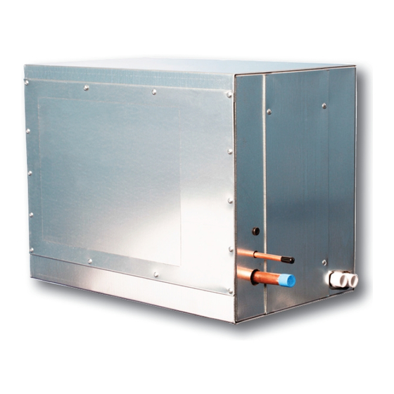
Bi-Flow Receiver
The Bi-Flow Receiver is designed for use with heat pump
systems, up to 5 tons, and with any typical refrigerants. The
receiver allows refrigerant a location to migrate to during the
heating cycle, minimizing head pressures. During cooling mode,
the receiver is empty, allowing the full refrigerant charge to be
utilized for cooling.
www.hi-velocity.com
Module RPM Refrigerant Module Installation (RPM-E) (4/5)
Refrigerant Module Installation (RPM-E) (4/5)
The receiver is a horizontal tank with a pair of dip tubes
extending to the bottom of the tank. These two tubes allow for
liquid refrigerant to be drawn from the tank regardless of the
direction of flow. For this reason, the receiver must be mounted
so that the inlet/outlets of the tank come out of the top of the unit.
Mounting brackets are located at the base of the unit for secure
mounting. The receiver is to be located on the liquid line of the
system, anywhere between the indoor and outdoor coils. As the
unit is of a bi-flow design, it does not matter which end faces
towards the indoor coil.
The inlet/outlet ports are constructed of steel and require the
use of a 35-45% Silver Solder and Flux for brazing. The use of
standard copper to copper solders may result in difficulty brazing
and the potential for a failure at the weld. Ensure that the tank is
protected from overheating while brazing and that any remaining
flux is cleaned from the unit. If installing outdoors, ensure that
the receiver is insulated and protected from the elements.
Freeze Stat
The RPM-E series cooling coil comes equipped with an
anti-freeze control mounted on the suction line. This freeze
control serves the purpose of preventing severe icing of the coil
in the event of an undercharge or low load on the coil. This
piece of equipment must be used at all times. Lack of use
of the freeze-stat will result in RPM-E related warranty
issues being voided. During start-up, it is acceptable to
jumper across the Freeze-Stat. This will prevent the freeze-
stat from shutting the system off while charging a new system
that may be low on refrigerant. Once charged and running,
this jumper must be removed and the Freeze-Stat connected to
the X1 and X2 terminals on the Printed Circuit Board. Should
wiring needs arise in which the outdoor unit is controlled
through another means of wiring, the Freeze-Stat should be
connected in series on the supply side of the control wiring.
Module RPM
© 1995-2009 Energy Saving Products Ltd.