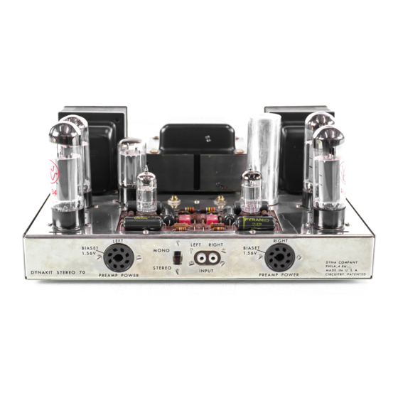
DYNACO Stereo 70 Інструкція по збірці - Сторінка 6
Переглянути онлайн або завантажити pdf Інструкція по збірці для Підсилювач DYNACO Stereo 70. DYNACO Stereo 70 16 сторінок. Series ii tube amplifier
Також для DYNACO Stereo 70: Посібник з реставрації (20 сторінок), Посібник з реставрації (5 сторінок), Посібник користувача (12 сторінок)

12
('1
Repeat step 11 for the left output trans-
former and the left screw terminal strip.
23
(v{
Connect the negative end of the other 50
MFD capacitor to lug #3 of the 7 lug strip
and the positive end to lug #1.
4
18
(v1
Repeat step 16 for connection of V2 and V3.
19
(VJ
Repeat step 17 for connection of V3 to left
power takeoff socket.
14
(v)
Repeat step 13 for right output transformer.
The blue lead is twisted with the green and
goes to pin #3 of V6 (8), green to pin #4,
while the blue-white and green-white, after
twisting together, are connected to pins #3
(8)
and #4
(8)
of V7.
32
("'1
T rim the leads of a 6800 ohm (blue -gray-
red) resistor to 1".
Connect one lead to
lug #
1
of the filter capacitor
(8).
Connect
the othe
l'
end to lug #4 of the filter capac itor.
30
("1
Connect one end of a 3" wire to lug It 1 of
the right s ide bias potentiometer
(8).
Con-
nect the other end to lug
#
1 of the left side
potentiometer
(8).
31
(t1"
Connect one end of a 5-1/4" wire to lug #8
of VI (8).
Connect the othe r end to lug
# 2
of the quad filter capacitor
(8).
24
(0'
Cut both leads of another 10,000 ohm (brown-
black-orange) resistor to 1". Connect one
end to lug #2 of the seven lug strip. Connect
the other end to lug
It 1
of the strip
(8).
25
0'
Connect one end of a 6" wire to lug #6 of
the
7
lug strip
(8).
Connect the other end
to the ground lug near the filter capacitor.
See pictorial.
26 (t..r Connect one end of a 6" wire to lug -# 3 of
the 7 lug
strip~,
(S).
Connect the other end
to lug
11 1
of the left bias potentiometer.
27 ("1 Connect one end of a 6" wire to lug #4 of
the
7
lug strip
(8).
Connect the other end
to the negative (top) lug of the selenium
rectifie
l'
(8).
29 (V'j Connect one end of a 3" wire to lug #3 of
the right side bias potentiometer
(8).
Con-
nect the other end to lug # 3 of the left side
bias potentiometer
(8).
28
(0'
Connect one end of an 8" wire to lug #2 of
the 7 lug strip (8).
Connect the other end
to lug #3 of the left bias control.
33
(.-1
Connect one end of a 15.6 ohm res istor to
the ground lug on base of V2 socket
(8).
Connect the other end to pin #8 of V2.
34
(VI
Strip both ends of a 5" wire 1/2".
Feed
one end through pin #
1
of V2
(8)
and connect
it to pin #·8 of V2 (8).
Feed the other end
through pin H8 of V3 (8) and connect to pin
411 of V3.
35
(0
Connect one end of a 4 -1/2" wire to pin
#
1
of V3 (8).
Connect the othe
l'
end to pin
#
8
of the left power takeoff socket (8).
36
M
Connect one end of the othe
l'
15.6 ohm
resistor to the ground lug at the base of
socket V7 (8).
Connect the other end to
pin #1 of V7.
Twist together a pair of 6" wires except
for 1-1/2" at each end.
Connect one end of
one wire to pin #2 of V7 (8).
Connect the
other wire to pin
#7
of V7
(8).
Connect one
of the other ends to pin #2 of V6.
Connect
the remaining end to pin
#7
of V6.
Twist together a pair of 7" wires except for
1-1/2" at each end.
Connect one end of one
wire to pin #2 of V6 (8). Connect the other
wire to pin # 7 of V6 (8). Dres s the pair to
the front panel of the chassis and over tothe
right power takeoff socket.
Connect one end
of the pair to pin #1 of the takeoff socket.
Connect the other of the twisted pair to pin
#2 of the takeoff socket.
20 (.q' Connect one end of a 5" wire to lug # 1 of
the 7 lug strip.
Connect the other end to
lug #6.
21
(0
Connect the negative end (-) of a 50 MFD
capacitor to lug #4 of the seven lug strip.
Connect the positive
(+)
capacitor lead to
lug #1.
22
(t:1"
Cut both leads of a 10,000 ohm (brown-black-
orange) res istor to 1".
Connect one end of
the resistor to lug #4 of the 7 lug strip and
the other end to lug #3.
13
(-7
Twist the blue and green leads from the left
output transformer together and connect the
green lead to pin
#4
of V3.
Connect the
blue lead to pin #3 of V3
(8).
Twist blue-
white and green-white together and connect
the blue-white lead to pin #3 of V2
(8).
Connect the green-white lead to pin #4 of
V2 (8).
17 (p1f
16
(0
15
(ur
Connect the center (common) lead of the
double (2 x .02) disc capacitor to lug #6 of
the 7 lug terminal strip.
Connect one of
the outside wires to lug
#5
of the strip
(8)
and the other outside wire to lug
#7
of the
strip
(8).
