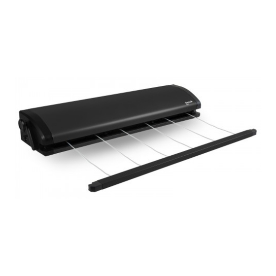
DAYTEK 4 LINE Інструкція з експлуатації - Сторінка 2
Переглянути онлайн або завантажити pdf Інструкція з експлуатації для Побутова техніка DAYTEK 4 LINE. DAYTEK 4 LINE 15 сторінок. Outdoor retractable clotheslines
Також для DAYTEK 4 LINE: Посібник з експлуатації (4 сторінок)

BEFORE YOU BEGIN
Please check the carton contains all the
required parts before installing the clothesline.
Your carton should contain the following:
1. Daytek 4/5/6 Outdoor Retractable Clothesline x 1
2. Wall to Wall fixing pack including detailed
installation instructions x 1
(Fixing pack provided is for installing to bricks and
timber walls only. For fixing to other type of wall
structures consult your local hardware specialist)
3. Bonus Daytek Clothespins
INSTALLATION OPTIONS
•
Wall to Wall – All fixing required included inside pack
•
Wall to Post – Requires additional Daytek Post Kit x 1
•
Post to Post – Requires additional Daytek Post Kit x 2
INSTALLATION INSTRUCTIONS
Important: Recommended installation height of line is
user height + 100mm (+4 inch) minimum. Maximum
wall to wall distance of 7 metres (23 feet). Ensure
selected position has a clearance of 1 metre (3.3 feet)
minimum on either side.
For timber wall installations, follow instructions and
use 5mm (13/64") diameter to drill all mounting hole
positions and discard plastic plugs when installing
cabinet and bracket.
Wall Mounting Hole Position Table:
Cabinet Mounting Distance
Model
(center to center hole positions – mm/inch)
4 Line
5 Line
6 Line
551 / 21.6
681 / 26.8
811 / 31.9
2
Maximum load capacity
Model
Maximum load capacity
4 LINE
16kg / 35.3lbs (4kg / 8.8lbs per line)
5 LINE
20kg / 44.1lbs (4kg / 8.8lbs per line)
6 LINE
24kg / 52.9lbs (4kg / 8.8lbs per line)
Tools required for installation:
•
8 metre (26 feet) measuring tape & pencil marker
•
Hammer
•
Hammer drill
•
Masonry drill bit (10mm or 25/64" diameter)
•
Socket set or adjustable wrench
•
1 spirit level (optional)
•
Twist drill 5mm (13/64") diameter (optional)
Bracket Mounting Distance
(center to center hole positions – mm/inch)
35 + 225 + 35 (1.4 + 8.9 + 1.4)
35 + 355 + 35 (1.4 + 14.0 + 1.4)
35 + 225 + 35 (1.4 + 8.9 + 1.4)
