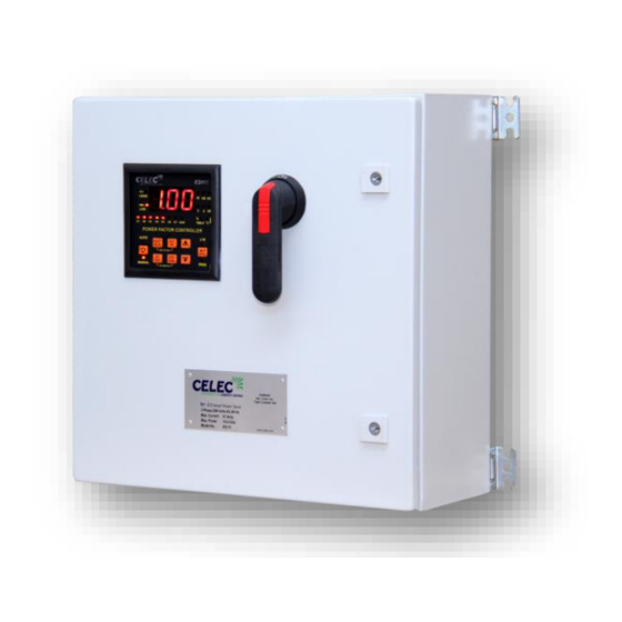
Celec ES-15 Посібник з монтажу в польових умовах - Сторінка 5
Переглянути онлайн або завантажити pdf Посібник з монтажу в польових умовах для Контролер Celec ES-15. Celec ES-15 10 сторінок.

Use this instruction
If 60 Amp circuit breaker is available in customer Main Breaker Panel.
ES-15 is designed for use with Main Breaker Panel Three Phase 120/208V AC WYE/Delta
Connection, up to 600 Ampere.
ES-15 unit should be mounted with four appropriate sized fasteners before connect to
Main Breaker Panel.
1.1 Power Connections
1.11 Switch off the external handle of load break switch (LBS), using panel key open the door of ES-15
exposing connections.
1.12 Locate Earth Terminal in ES-15, connect the earth wire to ES-15 Earth Terminal. Connect the other
side of earth wire to main breaker panel ground rod. Ensure all mechanical connections are secure
and making full contact.
1.13 Locate existing 3 Pole 60 Amp Circuit Breaker in the Main Breaker Panel.
Connect the wire L1 to Phase 1 of 60 Amp circuit breaker.
(b) Connect the wire L2 to Phase 2 of 60 Amp circuit breaker.
(C) Connect the wire L3 to Phase 3 of 60 Amp circuit breaker.
1.14 Qualified Representative must inspect size of cable minimum 6 AWG.
1.15 Connect power cables to Load Break Switch of ES-15.
1.2 Current Sensor Connections
1.21 Open one side of Split CT (Current Sensor). Clip the CT on the wire L3 before main Circuit
Breaker Panel.
1.22 Locate Terminal Block T2 (S1-S2) in ES-15.
1.23 Qualified Representative line side of Main Panel should connect the wires 18-22 AWG from external
CT to T2 (S1-S2), preferably twisted together.
1.24 Firmly secure current sensor to line side (L3) of main circuit breaker.
______________________________________________________________________________________
Field Installation Manual
Connection Type # 1
ES-15
5
