HiBoost F10G-5S-LCD Посібник користувача - Сторінка 7
Переглянути онлайн або завантажити pdf Посібник користувача для Подовжувач HiBoost F10G-5S-LCD. HiBoost F10G-5S-LCD 18 сторінок.
unusable signal quality can cause oscillation, this is why it is important to fully
understand the LCD indications on your booster, as they will help you identify and
solve any potential issues.
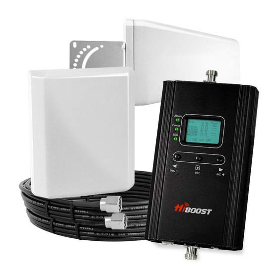
The LCD indicates the status of the booster system.
4 UNDERSTAND THE PORTS, LCD and LED STATUS,MGC
4.1 Repeater ports
1) Outdoor port: connected with the donor antenna by cable.
2) Indoor port: connected with server antenna directly or by cable.
3) DC 12V: connected with power supply.
4.2 LCD Features
After the booster is powered on, uplink (UL) and downlink(DL) gain and DL output
power are displayed. "Band"– Shows the working frequency. Below is a list of the
frequencies displayed corresponding to the Band display shown on the screen.
Frequency
700MHz Lower A/B/C blocks
700MHz Upper C block
CDMA800&GSM850&UMTS850
PCS1900
AWS2100
"UL (dB)""DL (dB)"– Gain Indication.
The displayed value shows real-time uplink and downlink gain. These values
will change slightly as the ALC or ISO makes changes to the gain to optimize
https://www.signalbooster.com/ | 1-855-846-2654 | [email protected]
Band display
LTE700
Cell800
PCS1900
AWS2100
7