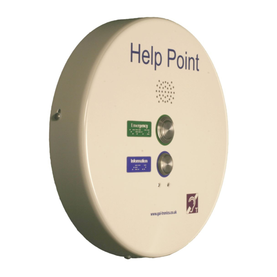
GAI-Tronics PHP400 Посібник з проектування, монтажу та експлуатації - Сторінка 8
Переглянути онлайн або завантажити pdf Посібник з проектування, монтажу та експлуатації для Телефон екстреної допомоги GAI-Tronics PHP400. GAI-Tronics PHP400 20 сторінок. Analogue version (1090/1099 series) with ampetronic hls-dm2 induction loop amplifier 230v ac power supply
Також для GAI-Tronics PHP400: Посібник з встановлення та експлуатації (20 сторінок), Посібник з встановлення та експлуатації (20 сторінок)

4. Select fixing screws or bolts appropriate to the type of wall or surface, suitable to
support the unit. Drill fixing holes to suit.
5. Separate the front and rear sections of the Help Point, taking care to disconnect
interconnecting cables as described in section 3.1.
6. Secure the rear section to the wall, making sure that the fixing holes are sealed to
prevent water ingress using nylon washers or other appropriate sealing methods.
7. Bring power and Ethernet cables into the unit through one or both of the cable entry
holes. Cables will normally be contained in conduit, but glands may also be used.
8. The power cable is terminated directly to the terminal block provided, and secured
using the cable restraint.
9. The ethernet cable should be left long enough to allow connection to the front section
(approximately 450mm from entry point) and terminated with an RJ45 plug.
10. Ensure that cable entries are sealed to prevent water ingress. If glands are used do
not over tighten – CAT5 UTP can be damaged by excess tightening. If only one cable
entry is used, the blanking plug fitted to the second position must be left in place.
11. Connect induction loop audio, dc power, ethernet and earth cables to the front
section of the case.
12. Apply power. The LED on the internal PSU should illuminate. After approximately 1
minute the red "heartbeat" LED inside the VoIP module should be visible flashing.
13. Fit the front section over the rear section and secure in place using the 4 security
screws.
Front section
Screw
terminals
M6
Earth
stud
Wiring scheme showing interconnection points between front and rear sections
INDUCTION LOOP AUDIO
RJ45
socket
+48V DC
CAT5
EARTH
400mm VoIP Help Point, 48V VoIP.
Bullet
connectors
+12V
EARTH
0V
Rear section
Screw
terminal
block
EARTH
0V
+48V DC
8
