HID Vertx CS V100 Посібник зі швидкого встановлення - Сторінка 6
Переглянути онлайн або завантажити pdf Посібник зі швидкого встановлення для Контролер HID Vertx CS V100. HID Vertx CS V100 9 сторінок.
- 1. QUICK START, VERTX (CS) V100 Door/Reader Interface Panel
- 2. Table of Contents
- 3. Introduction
- 4. Parts List (Included)
- 5. Product Specifications
- 6. Cable Specifications
- 7. Overview
- 8. Step 1 Preparations
- 9. What You Need before Getting Started
- 10. Step 2 Hardware Installation
- 11. Mounting Instructions
- 12. Wiring Vertx
- 13. Contact Information
VertX V100 (CS) Quick Installation Guide
3. RS-485 Connections: Connect the V100 to the V1000 through the RS-485 cable. See the V1000
Quick Install Guide for further information.
CAUTION: The V1000 RS-485 Ports 1 & 2 (P1) are a common bus and therefore cannot have
duplicate Interface Addresses assigned. The same is true of the V1000 RS-485, Ports 3 & 4 (P4).
For example, Interface Address 0 (factory default) cannot be assigned to both Ports 1 & 2 (P1).
4. Interface Address – Set the interface address by turning the Address dial. Ensure that
the V100 Interface Address is documented in the Hardware Installation Worksheet (found
in the back of the HID VertX V1000 Quick Install guide).
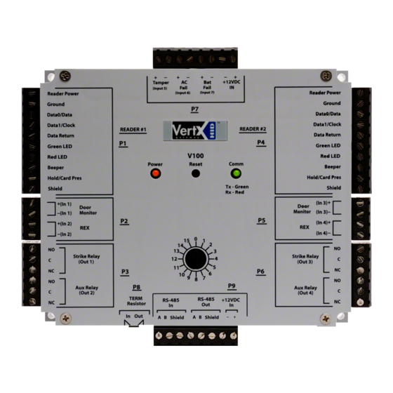
5. Output Connections – All Output connections are used for general
purpose controls. The following table shows where the various outputs are
located. Pin numbers shown use the convention "NO/C/NC".
For example, Output 1, V2000: P3 Pin1 is NO (Normally open) and Pin 2 is
C (Common) and Pin 3 is NC (Normally closed).
Note: Relay contacts are rated for 2Amps @ 30VDC.
Output
number
P3 Pins 1/2/3
1
Strike (lock)
P3 Pins 4/5/6
2
Aux Relay 1
P6 Pins 6/5/4
3
Strike (lock)
P6 Pins 3/2/1
4
Aux Relay 2
August 2005
V2000
V1000
P14 Pins
2/3/4
Relay 1
P11 Pins
6/5/4
Relay 2
2005 © HID Corporation. All rights reserved.
V100
V200
P3 Pins 1/2/3
P3 Pins 2/3/4
Strike (lock)
Relay 1
P3 Pins 4/5/6
P6 Pins 3/2/1
Aux Relay 1
P6 Pins 6/5/4
Strike (lock)
Relay 2
P6 Pins 3/2/1
Aux Relay 2
V300
P1 Pins 1/2/3
P1 Pins 4/5/6
P1 Pins 7/8/9
P2 Pins 1/2/3
Page 6 of 9