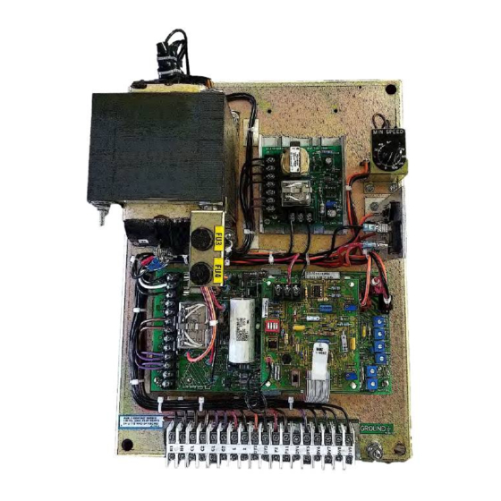
Dynamatic 4050 Інструкція з експлуатації - Сторінка 7
Переглянути онлайн або завантажити pdf Інструкція з експлуатації для Контролер Dynamatic 4050. Dynamatic 4050 13 сторінок. With dancer position
Також для Dynamatic 4050: Інструкція з експлуатації (15 сторінок), Інструкція з експлуатації (13 сторінок), Інструкція з експлуатації (14 сторінок)

Modification PCB Mounting
If you have purchased a complete controller this section may be passed over and you may proceed to
General Description.
1. Place the Main PCB in front of you with the long dimension in a horizontal position and the
terminal strip to the left.
2. Remove the DIP switch by pulling it straight out of the receptacle, RECP 1. Then, peel the adhesive-
backed label off the other half of RECP 1.
3. Insert the arrow-type locking head of the four nylon stand-offs supplied into the four 0.188"
diameter holes in the main PCB and press in. The tabs will snap out to lock the stand-offs
permanently in position.
4. Hold the modification PCB assembly over the stand-offs with the ribbon connector toward you
and insert the ribbon connector plug into RECP 1. Be careful to see that all 16 pins are started
properly into the receptacle before pressing the plug in.
5. Align the holes in the modification PCB assembly over the stand-offs and press over the tapered
posts until the locking flanges snap out to lock the board in position.
General Description
The Dancer Position modification converts the standard 4000 and 4050 controllers into a position control
system. The feedback quantity to the Main PCB becomes the position of a Dancer Operated
potentiometer rather than the drive output shaft velocity. The steady state position of the "dancer" is
actually controlled by adjusting the drive velocity so that a constant take-up reel, outer edge tangential
velocity, equal to the line speed, is maintained. The modification circuit includes a supplementary clutch
current bandpass filter circuit and a position rate circuit to provide the lead compensation necessary for
stability. The current gains are adjustable so that the dynamic response of a specific system can be tuned.
Visual Inspection
1. Before proceeding to the set-up procedure, check the controller for any damage that may have
occurred during shipment, such as loose connections and damaged wire or components.
2. Check all interconnection wires for conformance to connection diagram and schematic as
supplied in this instruction sheet.
3. Check the Operator's controls (which are supplied by customer) to see if they are connected
properly per the connection diagram. This includes the Dancer Position pot R5 and the Start and
Stop pushbutton controls.
Preliminary Adjustment
Perform the following preliminary adjustments (with no power applied to the controller)
A. Operator's Controls (supplied by customer unless specified)
1. Dancer Position Potentiometer R5
7
