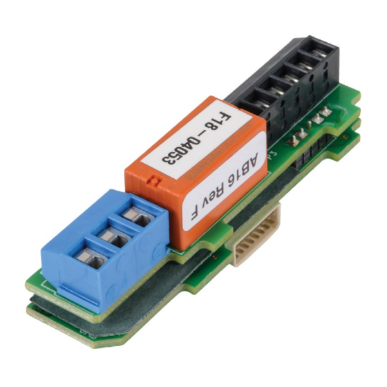
AutomationDirect IronHorse GSDA-AI-A8 Посібник користувача - Сторінка 10
Переглянути онлайн або завантажити pdf Посібник користувача для Блок управління AutomationDirect IronHorse GSDA-AI-A8. AutomationDirect IronHorse GSDA-AI-A8 12 сторінок. Analog module

Parameter
Parameter Name
Minimum Supported Framework
5
Version
Maximum Supported Protocol
6
Version
7
Serial Number (Major)
8
Serial Number (Minor)
GSDA-AI-A8's Target Speed to Drive
20
@ 4mA Input Current
GSDA-AI-A8's Target Speed to Drive
21
@ 20mA Input Current
22
4mA Input Trim
23
20mA Input Trim
Actual (S1 tach) Speed from Drive
40
needed to Produce 4mA Output
Current from GSDA-AI-A8
Actual (S1 tach) Speed from Drive
41
needed to Produce 20mA Output
Current from GSDA-AI-A8
42
4mA Output Trim
43
20mA Output Trim
Page 10
The lowest software "framework" version that is compatible with this card�
The protocol version is a code which identifies the highest (most-recent)
version of the protocol with which this card is compatible�
These parameters are reserved for future use as an electronic serial number
and are unique to each manufactured unit�
4-20 mA Input Scaling Parameters
This is the Target Speed setting that the GSDA-AI-A8 makes available to its
GSD8 Drive when there is 4mA of current flowing through the GSDA-AI-A8's
Input Loop terminals� The setting is in the GSD8 Drive's "Engineering Units",
just as if the Target Speed was being entered on the GSD8 Drive itself� This
setting is limited by the GSD8 Drive's Minimum Display setting�
This is the Target Speed setting that the GSDA-AI-A8 makes available to its
GSD8 Drive when there is 20mA of current flowing through the GSDA-AI-A8's
Input Loop terminals� The setting is in the GSD8 Drive's "Engineering Units",
just as if the Target Speed was being entered on the GSD8 Drive itself� This
setting is limited by the GSD8 Drive's Maximum Display setting� This setting
should also be greater than the setting for Parameter 20, above�
Used to compensate for minor inaccuracies in the overall system that is
connected to the GSDA-AI-A8's Input Loop terminals� This "trim", which has a
range that goes both positive and negative, affects the 4mA endpoint of the
GSDA-AI-A8's input range� To return to the factory-calibrated 4mA endpoint,
set this parameter to a value of zero�
Used to compensate for minor inaccuracies in the overall system that is
connected to the GSDA-AI-A8's Input Loop terminals� This "trim", which has a
range that goes both positive and negative, affects the 20mA endpoint of the
GSDA-AI-A8's input range� To return to the factory-calibrated 20mA endpoint,
set this parameter to a value of zero�
4-20 mA Output Scaling Parameters
This is the Actual Speed (tach) value that the GSDA-AI-A8 translates into 4mA
of current flow through the GSDA-AI-A8's Output Loop terminals� The setting
is in the GSD8 Drive's "Engineering Units", just as if the Tach Display was being
viewed on the GSD8 Drive itself�
This is the Actual Speed (tach) value that the GSDA-AI-A8 translates into 20mA
of current flow through the GSDA-AI-A8's Output Loop terminals� The setting
is in the GSD8 Drive's "Engineering Units", just as if the Tach Display was being
viewed on the GSD8 Drive itself�
Used to compensate for minor inaccuracies in the overall system that is
connected to the GSDA-AI-A8's Output Loop terminals� This "trim", which
has a range that goes both positive and negative, affects the 4mA endpoint
of the GSDA-AI-A8's Output range� To return to the factory-calibrated 4mA
endpoint, set this parameter to a value of zero�
Used to compensate for minor inaccuracies in the overall system that is
connected to the GSDA-AI-A8's Output Loop terminals� This "trim", which
has a range that goes both positive and negative, affects the 20mA endpoint
of the GSDA-AI-A8's Output range� To return to the factory-calibrated 20mA
endpoint, set this parameter to a value of zero�
IronHorse GSDA-AI-A8 User Manual – 1st Edition – 06/13/2019
Description
