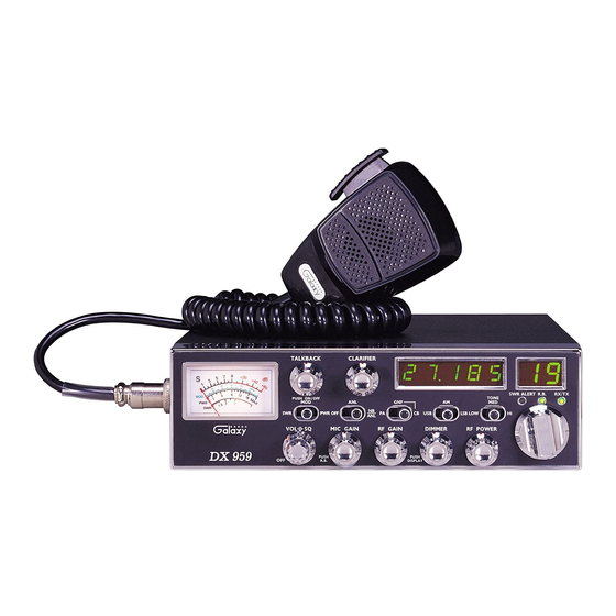
Galaxy DX 959 Посібник користувача - Сторінка 4
Переглянути онлайн або завантажити pdf Посібник користувача для Радіо Galaxy DX 959. Galaxy DX 959 12 сторінок. Solid state citizens band am/ssb mobile transceiver

TUNING THE ANTENNA FOR OPTIMUM S.W.R
Since there is such a wide variety of base and mobile antennas, this section
will strictly concern itself to the various types of mobile adjustable antennas.
Because the antenna length is directly related to the channel frequency, it
must be tuned to resonate optimally on all channels of the transceiver.
Channel 1 requires a longer antenna than Channel 40 because it is a lower
frequency.
Due to the various methods of adjusting antennas for proper S.W.R., we
have chosen what we think is the optimum method:
A. Antenna with adjustment screws (set screws).
1. Start with the antenna extended and tighten the set screw lightly enough
so that the antenna can be lightly tapped with your finger for easy
adjustment.
2. Set your transceiver to Channel 20. Press the PTT (push-to-talk) switch,
and tap the antenna (making it shorter). The S.W.R meter will show a
lower reading each time the antenna is tapped. By continuing to shorten
the antenna, you will notice the S.W.R reading will reach a low point
and then start rising again. This means that you have passed the
optimum point for Channel 20.
Extend the antenna a short distance and again follow the procedure above.
When the lowest point has been reached, switch to Channel 1 and then to
Channel 40 and compare S.W.R readings. They should be almost equal.
The proper setting is achieved when the SWR is 1.5 or
below, and when it has the same reading for channels 1
and 40.
B. Antennas which must be cut to proper length
1. Follow the same procedure as above, but adjust the length by cutting in
1/8" increments until a good match is obtained.
2. Be very careful not to cut too much at one time, as once it is cut, it can
no longer be lengthened.
3. The whip is easily cut by filing a notch all the way around and breaking
the piece off with pliers.
NOTE
- 5 -
If you're having difficulties in adjusting your antenna, check the following:
a.
All doors must be closed when adjusting the antenna
b. Make sure the antenna base is grounded.
c.
Check your coaxial cable routing (it may be pinched when routed into
the car)
d. Try a different location in your car (keeping in mind the radiation pattern
you wish.)
e.
Is the antenna perfectly vertical?
f.
Try a different location in your neighborhood. Stay away from large
metal objects when adjusting (metal telephone or lamp post, fences, etc.)
The transceiver will operate into an SWR of 2 to 1
indefinitely and sustain an SWR of 20 : 1 for a maximum
of 5 minutes at rated operating conditions.
EXTERNAL SPEAKER
The external speaker jack (EXT SP.) on the rear panel is used for remote
receiver monitoring. The external speaker should have 8 ohms impedance
and be able to handle at least 4 watts. When the external speaker is plugged
in, the internal speaker is disconnected.
PUBLIC ADDRESS
To use the transceiver as a public address system, connect an external 8
ohms speaker (4 watts minimum) to the PA. SP. jack located on the rear
panel. Direct speaker away from the microphone to prevent acoustic
feedback. Physical separation or isolation of the microphone and speaker is
important when operating the PA at high output levels.
NOTE
- 6 -
