Galaxy Audio Any Spot AS-1100 Посібник із швидкого старту
Переглянути онлайн або завантажити pdf Посібник із швидкого старту для Мікрофонна система Galaxy Audio Any Spot AS-1100. Galaxy Audio Any Spot AS-1100 2 сторінки. Wireless personal monitor
Також для Galaxy Audio Any Spot AS-1100: Посібник користувача (9 сторінок), Посібник користувача (9 сторінок)
GAL A X Y AUDIO
Wireless Personal Monitor
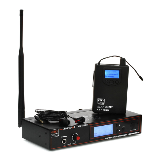
Included Components
1.
1.
AS-1100T x1
2.
AS-1100R x1
3.
EB4 Ear Buds x1
4.
MREWD Rack Kit x1
3.
5.
Antenna x1
6.
Power Supply x1
7.
Quick Start Guide x1
5.
Setup
1
Insert the 5.5mm plug into the DC input
jack, plug the wall wart into a 120VAC
outlet.
Dual Rack Mounting
(Optional)
1
Screw one short rack ear on the left side
of the first transmitter, and one coupler
half onto the right side of the same
transmitter using the provided screws.
2
Press the "SET" button, the display will
flash "GROUP". Use the up and down
buttons to select a group number. Press
set again, the display will flash "CHANNEL".
Use the up down buttons to select a
channel number.
2.
7.
4.
6.
2
Input Connection (XLR): Connect a
shielded XLR microphone cable to the
transmitter's left and right XLR input,
connect the other end into your signal
source's left and right outputs.
2
Screw one short rack ear on the right
side of the second transmitter, and one
coupler half onto the left side of the
same transmitter.
3
Insert Two AA Alkaline Batteries into the
Receiver.
Optional Accessories
1.
GAL A X Y AUDIO
EB6 Ear Bud Upgrade
Q uick Start Guide
Wireless Personal Monitor
AS-1100
Included Components
Optional Accessories
What May be Needed
1.
AS-1100T x1
1.
2.
7.
1.
EB6 Ear Bud Upgrade
1.
2.
to Rack
2.
AS-1100R x1
2.
EB10 Ear Bud Upgrade
(Not Included)
3.
EB4 Ear Buds x1
3.
Unlimited Receivers
1.
Rack Screws 10/32 x .75",
4.
MREWD Rack Kit x1
can be added
3.
Phillips Truss Head Screws
2.
EB10 Ear Bud Upgrade
5.
Antennas x1
3.
4.
4.
EXTBNC: BNC Cable
2.
#2 Phillips Head
6.
Power Supply x1
for Front Mounting Antenna
Screwdriver
7.
Quick Start Guide x1
(4 lengths available)
4.
5.
5.
CN-BNCPM: BNC Connector
5.
6.
for Front Mounting Antenna
1.
2.
Setup
Single Rack Mounting
(Optional)
1
2
3
4
1
3.
Unlimited Receivers
Insert the 5.5mm plug into the DC input
Input Connection (XLR): Connect a
Input Connection (1/4"): Connect a 1/4"
Attach the antenna to the antenna jack
Attach the long and short rack ears to
jack, plug the wall wart into a 120VAC
shielded XLR microphone cable to the
cable to the transmitter's left and right
and position at a 45 angle if possible.
o
either side of choice using the provided
outlet.
transmitter's left and right XLR input,
1/4" input, connect the other end into
screws. Align and screw into the rack.
connect the other end into your signal
your signal source's left and right outputs.
source's left and right outputs.
can be added
Dual Rack Mounting
(Optional)
Operation
1
2
3
4
1
Screw one short rack ear on the left side
Screw one short rack ear on the right
Align both transmitters so that the coupler
Align the dual transmitters to the rack
Press and hold the Power button for 3
of the first transmitter, and one coupler
side of the second transmitter, and one
halves fit, and screw them together.
and screw into the rack.
seconds to power on the Transmitter.
4.
half onto the right side of the same
coupler half onto the left side of the
EXTBNC: BNC Cable
transmitter using the provided screws.
same transmitter.
2
3
4
5
6
for Front Mounting Antenna
Press the "SET" button, the display will
Insert Two AA Alkaline Batteries into the
Turn the Level knob clockwise to power
Repeat step 2 on the Receiver so that the
Insert the ear buds into the receiver and
flash "GROUP". Use the up and down
Receiver.
on the Receiver.
Receiver matches the same Group and
adjust the volume to a comfortable level.
buttons to select a group number. Press
Channel number.
set again, the display will flash "CHANNEL".
Use the up down buttons to select a
channel number.
(4 lengths available)
5.
CN-BNCPM: BNC Connector
for Front Mounting Antenna
3
Input Connection (1/4"): Connect a 1/4"
cable to the transmitter's left and right
1/4" input, connect the other end into
your signal source's left and right outputs.
3
Align both transmitters so that the coupler
halves fit, and screw them together.
4
Turn the Level knob clockwise to power
on the Receiver.
1.
2.
3.
4.
5.
4
Attach the antenna to the antenna jack
o
and position at a 45 angle if possible.
4
Align the dual transmitters to the rack
and screw into the rack.
5
Repeat step 2 on the Receiver so that the
Receiver matches the same Group and
Channel number.
Quick Start Guide
AS-1100
What May be Needed
to Rack
(Not Included)
1.
Rack Screws 10/32 x .75",
Phillips Truss Head Screws
2.
#2 Phillips Head
Screwdriver
1.
2.
Single Rack Mounting
(Optional)
1
Attach the long and short rack ears to
either side of choice using the provided
screws. Align and screw into the rack.
Operation
1
Press and hold the Power button for 3
seconds to power on the Transmitter.
6
Insert the ear buds into the receiver and
adjust the volume to a comfortable level.