Galaxy Control Systems 635 Series Робочий аркуш - Сторінка 3
Переглянути онлайн або завантажити pdf Робочий аркуш для Панель керування Galaxy Control Systems 635 Series. Galaxy Control Systems 635 Series 5 сторінок. System galaxy installation worksheet
635-series Hardware Install QRS
This document lists things you must do to install the System Galaxy hardware.
Hardware Installation Steps
IMPORTANT SAFETY: Observe polarity when wiring the orange connectors to the power harness (Red = 12 VDC; Black = ground). Do not remove heat-shrink
from wire-pairs unless you are wiring a connector – i.e. leave heat-shrink in place on any empty slots. Do not short wires together when power is applied.
Failure to observe safety precautions can result in equipment damage, injury, electrical shock, or undesirable performance.
1.
Mount the controller to the wall in a clean dry place and apply power to power supply only.
Do not apply power to the boards, yet.
2.
Install the Battery that came with the controller - observing polarity (Red = 12 VDC; Black = ground).
3.
Using your multimeter, verify the power supply is producing +12VDC (must be between +12.0 to +13.6 VDC).
4.
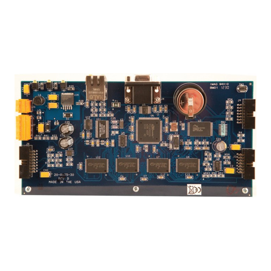
Install the CPU Board in the first slot and connect the Data Ribbon Cable to the I2C Buss on the CPU.
See
635 Hardware Installation
5.
Connect power wires (harness) to orange power connector on the CPU Board (observing polarity).
See
635 Hardware Installation
6.
Connect to CPU using serial cable + TeraTerm (
CPU IP Address:
TeraTerm settings:
(optional config tool)
Web Config Tool:
Web Config Tool Guide
7.
Configure the CPU network settings using the information from your Worksheet.
(
See
635 Hardware Installation
CPU's IP Address, Subnet, and Gateway addresses.
•
Cluster ID number
•
Panel Unit number
•
CPU board number
•
Event Server IP Address settings into Event Server-1
•
8.
Install the DRM Boards one at a time as follows:
Configure a valid Board Address on the DRM dipswitch (
a)
Install the DRM Board into the next available slot and connect the Data Ribbon Cable to the board. (
b)
Connect power wires (harness) to orange power plug on the DRM Board – observing polarity! (
c)
At the CPU (terminal emulator or web tool), verify the new board comes online:
d)
• in TeraTerm type the "boards" command to find the new board.
• In Web Config Tool go to the Panel Status page to find new the board.
• Notice: It can take up to 45 seconds for the board to appear on the CPU Database after ribbon cable is
attached. Board must have power.
Repeat A through D for each board in the controller.
e)
Continue on next page ...
See
635-Hardware Installation
Guide, Chapter 2 Step-4.1
Guide, Chapter 2 Step-3 for wiring the 635 CPU plug
192.168.0.150 (default factory)
Bits per Second = 57,600K
Parity = None
TeraTerm Galaxy USB X:\Auxiliary\System Galaxy\FTS635\Factory Test\ Teraterm\teraterm
PC/Laptop must be on the same network segment as the CPU to it by the mac address.
Web Config Tool Galaxy USB X:\Utilities\Galaxy_635_Web_Server_V107.exe
Guide, Chapter 2 Step-6.1 for using TeraTerm and Step-6.2 for Web Config Tool
(
See
Guide, Chapter 2 Step-2
optionally, use Cat-5e cable + Web Config Tool
Data Bits = 8
Stop Bits = 1
635 Hardware Installation
Guide, Chapter 2
1-16 is valid; each board must be unique
)
Flow Control = None
)
)
). (
Step 4.2.3
Step 4.2
)
Step 3
.exe
*
)
)
Page 3 of 5