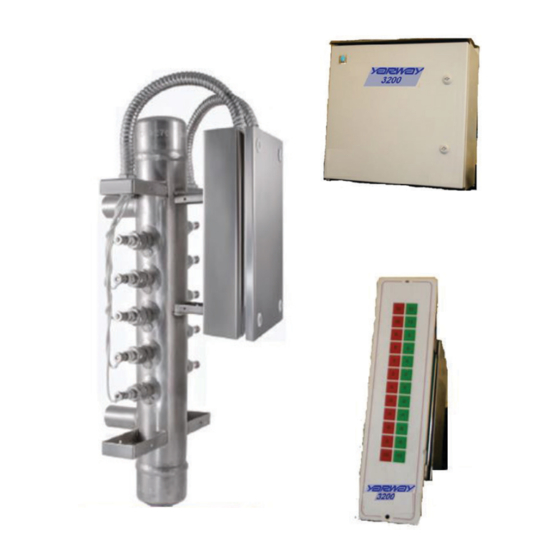
Emerson 3200 Інструкції з монтажу, експлуатації та технічного обслуговування - Сторінка 3
Переглянути онлайн або завантажити pdf Інструкції з монтажу, експлуатації та технічного обслуговування для Вимірювальні прилади Emerson 3200. Emerson 3200 15 сторінок. Electronic water level gauge
Також для Emerson 3200: Посібник користувача (20 сторінок)

YARWAY 3200 ELECTRONIC WATER LEVEL GAUGE
INSTALLATION, OPERATION AND MAINTENANCE INSTRUCTIONS
4 PACKAGING AND INSTALLATION
The Yarway 3200 with the column is packed
in one crate weighing approximately 200 lb
(91 Kg). Prior to installing this equipment, clean
all packing material from around the unit and
inspect for any damage that may have occurred
during shipment.
The purchaser must file any claims for loss or
damage with the transport carrier.
Installation
4.1 Location of the Electronics
Water with low conductivity requires higher
sensitivity. The highest sensitivity limits the
cable distance between probe and electronic
module to 65 ft (20 m). The intermediate
sensitivity places an upper limit of 165 ft (50 m)
on the cable distance. The lowest sensitivity
allows the cable distance to be up to 500 ft
(152 m). A plug-in module permits selection
of the conductivity range of the unit. Use the
highest conductivity mode where possible. The
coolest, most accessible location for mounting
the electronics is preferred.
IMPORTANT
Install the Electronic enclosure on a steel or wood
structure with minimum 1/4 in. (6 mm) bolts that has
adequate support strength for the enclosure weight.
4.2 Pressure Vessel
The pressure vessel is fixed to the steam
drum either by being welded directly to the
isolating valves or welded to flanges that
mate to existing flanges on the steam drum
tapping points. A steam inlet line must be
installed to provide a free flow of steam to the
column. Install valves in the steam line with
stem horizontal. The steam line must slope
down toward the column (a slope of 2% is
recommended). Ideally, the return water leg
should be horizontal. This leg may, however, be
sloped down to the drum, in which case it must
be insulated. In no case should the steam line
be insulated.
FIGURE 1
Vessel Installation
IMPORTANT
Consult the factory if conditions require the use
of other types of fittings or special mounting
configurations. All welding should be done in
accordance with approved procedures as required by
applicable specifications. Select and install isolation
and blowdown valves as outlined in the latest edition
of the ASME Power Boiler Code, Section 1. The valves
should be capable of tight shut-off.
The material of construction is normally carbon
steel. Other materials are available to satisfy
application design requirements.
Horizontal Probe Column: Designed for
2000 psi (138 bar) and 3000 psi (207 bar) and 5
or more probe levels.
A weather shield is recommended for outside
installations.
Remove the metal probe covers until the
system is placed in service and a satisfactory
inspection of all the probes and the associated
wiring is completed. Refer to Section 4.3 to
install the probe and Swagelok nut.
NOTE
All cover screws must be tightened and reinstalled if
removed.
If the probe cover is damaged and cannot be
properly secured, it may cause a short circuit
and must be replaced.
3
