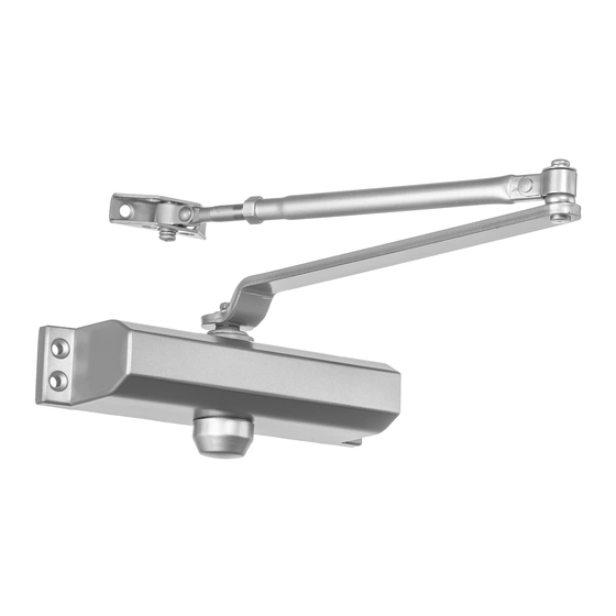
Dynasty DYN-2000 Інструкція з монтажу - Сторінка 2
Переглянути онлайн або завантажити pdf Інструкція з монтажу для Система відкривання дверей Dynasty DYN-2000. Dynasty DYN-2000 2 сторінки. Door closers

REGULAR ARM (PULL SIDE) Mounting
6-1/2
A
1-3/4(44.4)
(165.1)
1-1/4(32)
1 (25 )
3/4(19)
8-3/16(208)
Speed
valves
DYN-2000,DYN-3000
Hinge
or
Pivot
Right hand door shown
Left hand door opposite
Dimensions are in inches(mm)
Do not scale drawing
INSTALLATION SEQUENCE
1. Select degree of opening and use dimensions shown or attached template to locate 4 holes on door for closer body
and 2 holes on frame for arm shoe.
2. Prepare door and frame for fasteners. See "Preparation for Fasteners", Figure 1, Page 1.
3. Install forearm/arm shoe assembly to frame using provided screws.
4. Mount closer on door using provided screws. SPEED ADJUSTING VALVE MUST BE POSITIONED TOWARD
HINGE EDGE
5. Install main arm to top pinion shaft, perpendicular to door. Secure tightly with provided arm screw/washer assembly.
6. Adjust length of forearm so that forearm is perpendicular to frame when assembled to preloaded main arm (see below
illustration). Secure forearm to main arm with provided screw/washer assembly
7. Snap pinion cap over shaft at bottom of closer. If the slim cover is packed, please fix it by provided screws.
8. Adjust the door closer, following instructions as shown on page 1.
Top View Typical Installation
Right hand door
SPEED
ADJUSTING
SCREW
Preload
PAGE 2
6-1/2
A
(165.1)
1-1/4(32)
3/4(19)
9-1/16(230)
Speed
valves
DYN-4000
Hinge
or
Pivot
DIM.A
OPENING
Size 2&3
6-1/2(165.1)
6-1/2(165.1)
To120°
4(101.6)
120°-180°
Left hand door
Optional "BC"
ADJUSTING SCREW
SPEED
ADJUSTING
SCREW
Preload
A
1-3/4(44.4)
3/4(19)
1 (25 )
1/2(12.7)
Speed
valves
Hinge
or
Pivot
Left hand door shown
DIM.A
Right hand door opposite
Size 4
Dimensions are in inches(mm)
Do not scale drawing
4(101.6)
INSTALLATION SEQUENCE
1. Select degree of opening and use dimensions shown or attached template to locate 4 holes on frame for closer body
and 2 holes on door for arm shoe.
2. Prepare door and frame for fasteners. See "Preparation for Fasteners", Figure 1, Page 1.
3. Install forearm/arm shoe assembly to door using provided screws.
4. Mount closer on door using provided screws. SPEED ADJUSTING VALVE MUST BE POSITIONED TOWARD
HINGE EDGE
5. Install main arm to top pinion shaft, perpendicular to door. Secure tightly with provided arm screw/washer assembly.
6. Adjust length of forearm so that forearm is perpendicular to frame when assembled to preloaded main arm (see below
illustration). Secure forearm to main arm with provided screw/washer assembly
7. Snap pinion cap over shaft at top of closer. If the slim cover is packed, please fix it by provided screws.
8. Adjust the door closer, following instructions as shown on page 1.
TOP JAMB (PUSH SIDE) Mounting
8-3/16
(208)
1-3/4(44.4)
6-1/2
1/2(12.7)
1-3/4(44.4)
(165.1)
DYN-2000,DYN-3000
Hinge
Pivot
OPENING
To120°
120°-180°
Top View Typical Installation
Left Hand Door
Right Hand Door
Optional "BC"
ADJUSTING SCREW
SPEED
ADJUSTING
SCREW
Preload
9-1/16
A
(230)
3/4(19)
1-3/4(44.4)
6-1/2
1-3/4(44.4)
(165.1)
Speed
valves
DYN-4000
or
DIM.A
DIM.A
Size 4
Size 2&3
6-1/2(165.1)
6-1/2(165.1)
4(101.6)
4(101.6)
SPEED
ADJUSTING
SCREW
Preload
PAGE 3
