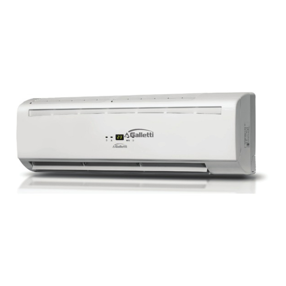
Galletti FM 23 Технічний посібник - Сторінка 11
Переглянути онлайн або завантажити pdf Технічний посібник для Кондиціонер Galletti FM 23. Galletti FM 23 20 сторінок. High wall-mounted fan coil units with bldc motor and incorporated valve 2.0 kw-3.7 kw

FM
7
WIRING DIAGRAMS
ABBREVIATIONS
Ts = set temperature
Tr = Room temperature
Ti1 = convector chilled water temperature
Ti2 = convector hot water temperature
AUX1 = hot water free contact
AUX2 = chilled water free contact
MTV1 = cooled motor driven valve
--------- Factory wiring
- - - - - Field wiring
DIPA-S1
SW1-5: unit address setting.
SW6: unit type setting: Master or slave.
Mode Configuration:
SW7=0; SW8=0; unit working in cooling/heating mode.
SW7=1; SW8=0; unit working in cooling mode only.
DIPB-S2
SW1: Occupation contact setting
SW2: Unit configuration setting:
0= 2-pipe system
SW3: On/Off valve configuration
0=w/o valve
1=with valve
SW4: Pre-heating setting:
0=36 °C
1=28 °C
SW5, SW6, S3 (by-pass jumper): Fan speed configuration.
I/O contacts:
L/N: Power supply: 230 Vac
Valve 1: Valve output On/Off -230 Vac.
(2 pipes: cooling/heating)
Valve 2: Valve output On/Off -230 Vac.
(4 pipes: heating only)
HEATING: Electric heater input/output - 230 Vac.
AI1: Return air temperature sensor - 1 (Tr).
AI2: Internal convector temperature sensor - 1 (Ti1).
AI3: Internal convector temperature sensor - 2 (Ti2).
AUX1: No-voltage contacts; ON: unit in heating mode.
AUX2: No-voltage contacts; ON: unit in cooling mode.
ON/OFF: Occupation contact
CN1~2: Stepper motor rate.
CN3: Serial BUS contacts.
CN4: Fan speed output - 230 Vac.
KEY: On/Off switch. The 20/24 type uses an electric control board
MTV2 = motor driven hot valve
FC66003740 - Rev 01
8
MASTER / SLAVE NETWORKS
The FM fan coil units are equipped with a PCB suitable for the implementation
of master/slave networks with up to 32 units.
Depending on the control panel used on the master unit it is possible to
implement two different types of master/slave control.
Global control communication
Master unit with IR remote control or a wired WALLPAD.
The master unit will transmit the settings to all slave units. During normal
operation the slave units can receive data from the wireless remote control
or the wall-mounted control.
After receiving the global commands from the master unit, all slave unit
settings will be replaced by the master settings.
In case of global control communication it is not possible to set different
settings on slave units, which will all work in the same manner.
Addressable communications
The master controller must be a wired wallpad.
The slave unit parameters are set as usual. After receiving the control
commands from the master unit, the addressed slave unit settings will be
replaced by the master settings
In that case using the WALLPAD it is possible to send customized instructions
to each of the units connected to the network.
Master unit function
The master unit sends the data referring to its settings to the slave unit.
The settings of the Master unit are: Unit On / Off, Mode, Fan Speed , Timer,
Clock, Temperature selection, sweep function and sleep function for use
from remote control.
The settings of the Master unit are: Unit On / Off, Mode, Fan Speed , Timer,
Clock, Temperature selection, sweep function and sleep function for use
from wall-mounted control.
All copying, even partial, of this manual is strictly forbidden
11
