AGS Merlin 1000S Посібник з монтажу, експлуатації та технічного обслуговування - Сторінка 7
Переглянути онлайн або завантажити pdf Посібник з монтажу, експлуатації та технічного обслуговування для Лабораторне обладнання AGS Merlin 1000S. AGS Merlin 1000S 10 сторінок. Gas utility isolation controller
Також для AGS Merlin 1000S: Посібник з експлуатації та встановлення (10 сторінок), Посібник з монтажу та експлуатації (12 сторінок), Посібник з монтажу та експлуатації (16 сторінок)

Merlin 1000S
Gas Utility Controller
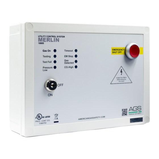
GAS DETECTED
Under normal working conditions this LED is off.
If the external Merlin detector connected detects gas this will illuminate and the gas valve will
shut off.
OFF = OK
RED = Gas detected.
CO2 HIGH
Under normal working conditions this LED is off.
If the concentration of CO
will illuminate and the gas valve will shut off.
OFF = OK
RED = the concentration of CO
3.3
EMERGENCY SHUT OFF
The Emergency shut off button is located on the front of the panel. There is also a facility for
remote shut off buttons to be wired in series.
The Emergency shut off button(s) will cut off the gas supply when activated.
To reinstate the system, the Emergency shut off button(s) will need to be reset and the panel
restarted.
3.4
BMS INTERGRATION
The Merlin 1000S can be integrated with a BMS to make or break a circuit on gas on/gas off,
(valve open or valve closed). This will tell the BMS whether or not power is being sent to the
solenoid.
There is a dip-switch located on the inside facia of the Merlin 1000S labelled [BMS SELECTION].
This is factory set in the 'off' position which signals the BMS on gas on/gas off.
When switched to the 'on' position, the 1000S will only signal the BMS on a fault, i.e. CO2 high
level detected, gas detected, EM Stop pressed, etc.
3.5
FIRE ALARM INTERGRATION
The Merlin 1000S can be integrated with a fire alarm to shut the gas supply automatically in the
event of a fire. The volt free fire alarm signal can be wired in series with any remote emergency
shut off buttons.
If there are no remote emergency stop buttons installed, wire this directly to the terminal
marked [EM REMOTE].
Rev: 05 Date: 29-10-18
in the air is at alarm level (relevant detector required), the LED
2
is at alarm level.
2
User & Installation Manual
7
