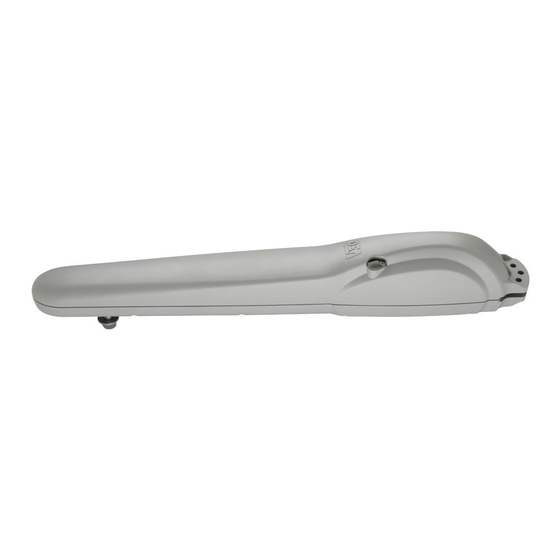
Dea STING/EN Інструкції з експлуатації та попередження - Сторінка 5
Переглянути онлайн або завантажити pdf Інструкції з експлуатації та попередження для Відкривач воріт Dea STING/EN. Dea STING/EN 18 сторінок. Electro-mechanical operator for swing gates

4.3 How to unlock the operator
WARNING Disconnect the power supply from the control panel before releasing the operator. In case you cannot turn the power
off, you will necessarily have to re-lock the motor in the position in which it was unlocked.
STANDARD VERSION UNBLOCKING
• Turn the cap placed on the back of MAC in order to discover the underlying shaped hole.
• Insert the release key inside the shaped hole paying attention to the direction of insertion (Pic. 8.a).
• Rotate 90 degrees (counterclockwise to unlock, clockwise to lock) the release key (Pic. 8.b).
STING VERSION UNBLOCKING
Once the lock placed on the release handle (that is protected by a plastic cover) is opened (Fig. 8.c), this will be raised (Fig. 8.d); at this
point, the STING is unblocked and the gate, in the absence of other impediments, is free to move. The reverse process, or the pushing to
the end stop and relocking the lock, restores the STING to working conditions.
WARNING Remember to protect the lock with the respective cover so that the operator is protected by water or powder (even when it
remains unlocked for a long time).
WARNING During this operation gate may perform uncontrolled movements: operate with extra care so to avoid any risk.
5 ELECTRICAL CONNECTIONS
WARNING To ensure an appropriate level of electrical safety always keep the 230V power supply cables apart (minimum 4mm in the
open or 1 mm through insulation) from low voltage cables (motors power supply, controls, electric locks, aerial and auxiliary circuits
power supply), and fasten the latter with appropriate clamps near the terminal boards.
WARNING To connect the encoder to the control panel, use only a dedicated cable 3x0,22mm
WARNING During the connection phase, fasten the electric cables with appropriate clamps near the terminal boards and, when possible,
unsheathe the cables to avoid they are too long.
Connection for 24V and 230V
• Remove the plastic cover positioned under MAC/STING (Pic. 9).
• Open one of four shaped holes and choose where the cable exit has to be (Pic. 10).
• Introduce the cable clamp and fix it by its nut (Pic. 11).
• Insert the power supply cable into the clamp (coming from the control panel): A quadrupole cable suitable for external applications
with a 4x1mm² section (or 3x1,5mm² for 24V operators)(minimum H05RN-F type) coming directly from the control panel (without any
connection and shunt box) and supplied by the installer (Pic. 12).
CLOSE
OPEN
10
24V
2(blue)
M
1(red)
.
2
230V
1(white)
CLOSE
2(blue)
COM
OPEN
3(black)
M
