Centrometal Bio-Tec 25 Технічний посібник - Сторінка 6
Переглянути онлайн або завантажити pdf Технічний посібник для Котел Centrometal Bio-Tec 25. Centrometal Bio-Tec 25 17 сторінок.
- 1. Technical Data
- 2. Delivery Package
- 3. Additional Equipment
- 4. Cleaning and Maintenance of the Boiler
- 5. Connection to the Chimney
- 6. Boiler Use
- 7. Connection to the Central Heating System
- 8. Boiler Start up
- 9. Boiler Thermal Protection
- 10. Thermal Fuse
- 11. Electric Connection
- 12. Boiler Regulation
Boiler / additional equipment positioning and assembly
2.0. BOILER / ADDITIONAL EQUIPMENT POSITIONING AND ASSEMBLY
The allocating of the boiler has to be carried out by the authorized person. We
suggest the allocation on the solid concrete basis, which height is between
50-100 mm. The boiler room has to be absolutely protected from freezing and
properly ventilated. The boiler has to be set up in order to enable its connecting to
the chimney (see point 3.) as well as its servising during the functioning process,
cleaning and maintenance (Image 1). The connection boiler to the central heating
system is obligatory through the one or more CAS water accumulators,
depending of the boiler's power. It is recommended to connect 50 liters water
accumulation to each 1 kW boiler power (i.e. for the 45 kW boiler minimal water
accumulation should be 2250 liters). The boiler should not be used without being
connected to the water accumulation tank. It must be connected to the CAS water
accumulator exclusively through an 3-way thermic valve ESBE VTC 512 (maintains
minimum temperature of return water into the boiler above 60°C), VTC 531
(maintains minimum temperature of return water into the boiler above 60°C),
LTC141 (keep minimal temerature of return water into the boiler above 60°C) or
Laddomat 21 (maintains minimum temperature of return water into the boiler above
63°C).
WARNING!
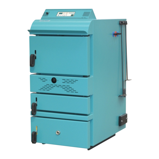
Flammable items must not be placed on the boiler and within the minimum
distances shown in Figure 1.
Image 1. Minimum distance from the room walls
min. 1000 mm
*valid for closest tank to the wall
6
*min. 1000 mm
min. 700 mm
Technical manual Bio-Tec
Cleaning of the flue gas chamber with flue gas tubes (Image 11.-DC):
- remove top back cover of the boiler casing (Image 11.-PD).
- unscrew four M8 nuts and remove the lid of top opening for flue gas tube
cleaning (Image 11.-GO).
- take out the wire fuse (Image 11.-ZO).
- unhook turbulator holder (Image 11.-DT) together with turbulators (Image 11.
-TU) from the shaft (Image 11.-DN).
- take out the turbulator holder (Image 11.-DT) together with turbulators (Image
11.-TU) from the flue gas chamber.
- clean flue gas tubes using a brush (Image 11.-CC) supplied with the boiler.
- remove turbulators (Image 11.-TU). from the turbulator holder (Image 11.-DT).
- clean spiral turbulators (Image 11.-TU) and place them back together with the
turbulator holder (Image 11.-DT) into flue gas tubes.
- hook the turbulator holder (Image 11.-DT) onto the shaft (Image 11.-DN).
- place back the wire fuse (Image 11.-ZO).
- place back the lids of bottom openings for the flue chamber cleaning (Image
11.-GO) to their original place and tighten them using screws (as before
removal) to get good air tightness during boiler operation.
- put the top back cover of the boiler casing (Image 11.-PD).
- take out the lids of lower openings for cleaning the flue gas chamber
(Image 11-DO).
- clean flue gas chamber throught the lower openings for cleaning
(Image 11- DO).
- place back the lids of lower openings for cleaning (Image 11.-DO) to its original
place and tighten them using screws to get good air tightness during boiler
operation.
In order to clean the boiler, there is no need to remove the refractory stone
(chamotte).
Technical manual Bio-Tec
Cleaning and mainternance of the boiler
27