Gantner 820679 Інструкція з монтажу - Сторінка 3
Переглянути онлайн або завантажити pdf Інструкція з монтажу для Замки. Gantner 820679. Gantner 820679 4 сторінки. Battery powered lock for mifare data carriers
Installation instructions
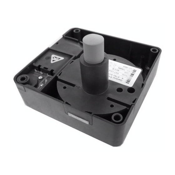
The GAT Lock 6010 F is suitable for lockers with metallic and non-metallic
doors and attaches to the inside of the locker door using four screws. A
hole is required in the locker door for the button.
Before installing all locks in a new system, complete a test installation
in one locker and a functional test with a corresponding data carrier.
Only once testing is successfully completed may the remaining locks be
installed in the same way.
NOTE! See the GAT Lock 6010 F manual for detailed installation
instructions.
Door opening
Depending on the hinge, locker doors can open to the right or left. Orientate
the electronics of the GAT Lock 6010 F according to the diagram below.
Right-hinged door
Locker
Locker door
GAT Lock 6010
View A
Button
Battery compartment
LED
Bolt
View A
Door width
The minimum allowed width for the locker door is 240 mm (9.45´´). If the
door is narrower than 240 mm, the lock will hit the locker when the door
is being closed.
4 mm (0.16´´)
4 mm
(0.16´´)
9 mm
(0.35´´)
17 mm
30 mm
(0.67´´)
(1.18´´)
www.gantner.com
Left-hinged door
Locker
GAT Lock 6010
View B
Button
LED
Battery compartment
View B
GAT Lock 6010
Locker door
to the door hinge
min. 240 mm
(9.45´´)
Button drill hole
A hole must be drilled into the locker door for the button. For non-metallic
locker doors, the diameter of the button drill hole is 23 mm. The reading
range depends on the type of data carrier used.
For metallic locker doors, different values apply for the button drill hole
and reading range (refer to the GAT Lock 6010 F manual).
Mounting
Right-hinged door
Locker door
22 mm
Bolt
• Use the correct screws according to the type of locker material, max. Ø
4 mm (0.16´´). The maximum allowed tightening torque of the screws is
2 Nm (1.47 lb-ft).
• Ensure that the button is centrally aligned in the drill hole.
• Ensure that the housing of the GAT Lock 6010 F does not contact the
inside of the locker body when opening/closing the locker door.
• Ensure that the battery compartment can be opened after mounting and
is not hindered by other components.
• Do not use any metallic labels on the locker door.
Valid from February 27
, 2017 • Technical data subject to modification without notice.
th
Reading range
Left-hinged door
72 mm
30 mm
64 mm
Fastening screws
GAT Lock 6010
Locker door
Number label
Instruction label
DB_GAT-LOCK6010F--EN_21.indd • Part No.: 985287
Button drill hole
Ø 23 mm
72 mm
22 mm
3