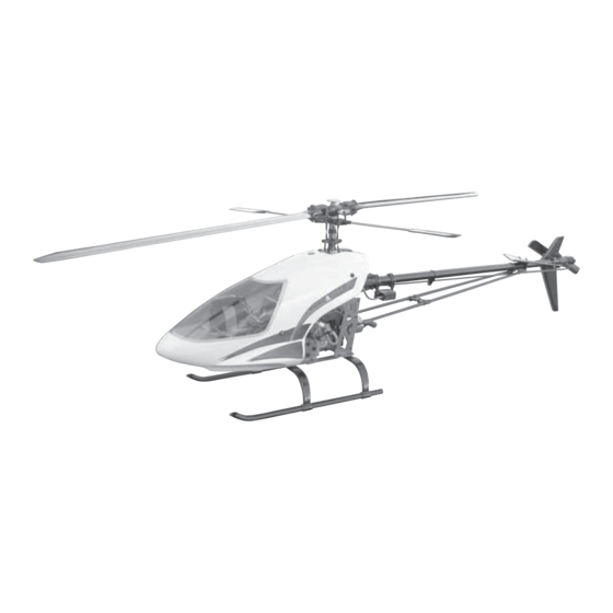
Century Helicopter Products Predator Max 90 Інструкція з експлуатації - Сторінка 13
Переглянути онлайн або завантажити pdf Інструкція з експлуатації для Іграшка Century Helicopter Products Predator Max 90. Century Helicopter Products Predator Max 90 20 сторінок.
Також для Century Helicopter Products Predator Max 90: Інструкція з експлуатації (20 сторінок)

61
The main rotor grips will accept rotor blades that have a root
thickness that is from 12mm to 18mm and have a 5mm hole.
Carbon Rotortech and wooden Aerotech blades are designed
for 5mm blades bolts.
M3x4 Set
Screws x 4
Assemble the landing skids onto the struts, note the correct
direction is to have the struts sweep forward. Position the rear
strut at approximately 37mm from the end and secure the skid
with the M3 set screw. Leave the front loose for now.
#HW6059 Tail Transmission
#CNBB511 x 2
Drive Shaft
#HW3057 Tail
Bevel Gear &
M5x10 Collar &
M3x5 Set Screw
M3x5 Set Screw
Insert the M3x5 set screw into the bevel gear and leave loose
until the transmission is fitted to the mechanics. Set the gear
mesh by running a single piece of paper between the bevel gear
and the main gear. Once in position, locktite the set screw.
#HW6001 M5x35
Shoulder Socket
Screw x 2 & M5
Locknut x 2
#HI6145 Ball Link Set
(26 long & 4 short)
#HW6192 Upper
Linkage Set (6 rods)
#HI6122 Landing
Struts x 2
~ 1 1/2"
[37mm]
#HW6123 10mm
Landing Skids x 2
63
65
#HI6060 Front Tail
Transmission
#HI6154
Torque Tube
Drive Coupler
& M4x5 Set
Screw
The rotor head pushrods for all versions of the Predator
will start from the basic lengths indicated here. Many of the
pushrods in the kit are pre-assembled, requiring only minor
length changes to suit the particular servo installation.
Location
Flybar Yoke to Washout (2)
Seesaw to Bell Mixer (2)
Swashplate to Bell Mixer (2)
CCPM Bellcrank to Servo (4)
Elevator Bellcrank to Servo (1)
Carburetor Arm to Servo (1)
CCPM Bellcrank to Swashplate (2)
All dimensions are measured
center to center of ball links.
Note: Ball links are designed to be
installed in one direction only. Look
carefully at the ball link ends to see that
on one side there is a ring around the
hole, this side presses over the steel
control balls.
M3x20
Socket
Screws x 4
& M3x10
Flat Washers
#HW6117
Landing
Gear Frame
M3x8 Socket Screws x 4
& M3 Locknuts x 8
Attach the landing gear frame to the mechanics with M3x8
socket screws and locknuts. Attach the landing gear with
M3x20 socket screws, M3x10 flat washers (against struts)
and locknuts, sliding the front skids into final position.
Secure the M3 set screws.
26mm Threaded
Hex Spacers x 3
#HW6062
Tailboom 795mm
#HW6062A Tailboom 825mm
#HW6063
Torque Drive Shaft 60/70 & SE
#HW6063A Torque Drive Shaft Max 90
Insert the 26mm hex spacers into the transmission half.
Pushrod
Rod
Length c/c
A
25mm
47mm
B
15mm
26mm
C
80mm
102mm
D
104mm
120mm
E
80mm
100mm
F
80mm
116mm
G
35mm
56.5mm
Clean side
faces
outwards.
around
locknut on
60/70 & SE
Max 90
62
Ring
mark
hole.
64
Note
top.
66
13
