Jamara 061260 Інструкція - Сторінка 4
Переглянути онлайн або завантажити pdf Інструкція для Передавач Jamara 061260. Jamara 061260 16 сторінок. Throttle left, throttle right
Також для Jamara 061260: Інструкція (16 сторінок), Інструкція (16 сторінок), Інструкція (16 сторінок), Інструкція (16 сторінок), Інструкція (16 сторінок)
IT
2.
Procedure di accensione
1. Mettere insieme tutti gli elementi.
2. Accendere la trasmittente.
3. Collegare la batteria alla ricevente.
4. Il LED rosso si accende in modo permanente ricevitore, il che significa che l'esistenza di un
vero e proprio segnale.
5. Il sistema è acceso e può essere utilizzato.
3.
Apagar secuencia
1. Desconecte la batería del receptor
2. Apague el transmisor
1
2
3
4
5
6
7
8
9
10
11
22
23
4
Accendere
Power ON
GB
2.
Power on
1. Connect all parts.
2. Switch on the transmitter.
3. Connect the receiver battery.
4. The receiver red LED indicator is solid indicating the presence of a correct signal.
5. Use the radio system.
Disabilita
Power OFF
3.
Shut down
1. Disconnect the receiver battery.
2. Switch off the transmitter.
12
13
14
15
16
17
18
19
20
21
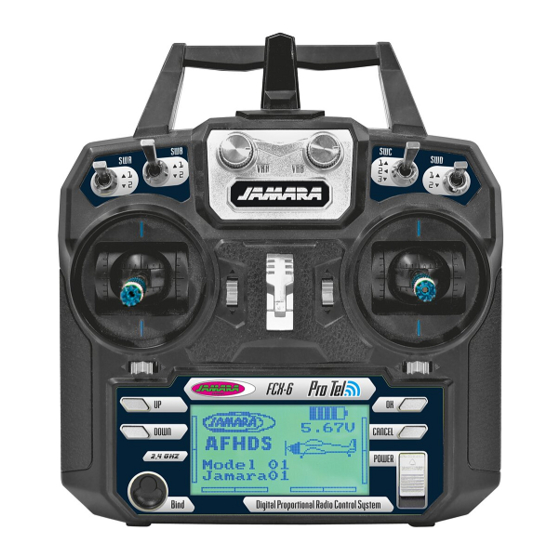
IT - Descripción gas sinistra
1
Antenna 2,4 GHz
2
Girare regolatoreVRB (Programmazione libera)
3
Interrutore B (Programmazione libera)
4
InterrutoreA (Programmazione libera)
5
Modo 2 = Stick gas / Direzionale
Modo 4 = Stick gas / Aileron
6
Gas trim
7
Modo 2 = Direzionale trim
Modo 4 = Aileron trim
8
Pulsante UP
9
Pulsante DOWN
10 LCD
11 Tasto di collegamento
12 Girare regolatore VAA (Programmazione libera)
13 Interrutore C (Programmazione libera)
14 Interrutore D (Programmazione libera)
15 Aggancion cinghia
16 Modo 2 = Stick aileron / elevator
Modo 4 = Stick elevator / direzionale
17 Elevator trim
18 Modo 2 = Aileron trim
Modo 4 = Direzionale trim
19 Invio (ENTER)
20 Exit / indietro
21 Interruttore on/off
22 Collegamento per cavo Simulatore
23 Vano Batterie
GB - Definition of key funktions throttle left
1
2,4 GHz Antenna
2
Rotary poteniometer VRB (free programmable)
3
Switch B (free programmable)
4
Switch A (free programmable)
5
Mode 2 = Throttle/Rudder stick
Mode 4 = Throttle/Aileron stick
6
Throttle Trim
7
Mode 2 = Rudder Trim
Mode 4 = Aileron Trim
8
Key up
9
Key down
10 LCD Display
11 Bonding button
12 Rotary poteniometer VAA (free programmable)
13 Switch C (free programmable)
14 Switch D (free programmable)
15 Hook
16 Mode 2 = Aileron/Elevator stick
Mode 4 = Elevator/Rudder stick
17 Elevator Trim
18 Mode 2 = Aileron Trim
Mode 4 = Rudder Trim
19 Enter button
20 Exit / Back button
21 Power switch
22 Simulator connecter
23 Battery box